
integrated circuit Improving absolute precision of ADC to balance battery voltage

The proposed circuit employs the Piccolo TMS320F28035 microcontroller, which features a 12-bit ADC capable of precise voltage measurements across multiple battery cells. Each cell's voltage will be conditioned using operational amplifiers configured to subtract the common mode voltage, thereby ensuring that the ADC operates within its optimal range.
The choice of operational amplifiers is critical; they must exhibit a high CMRR, typically above 80 dB, to effectively reject the common mode signals. Additionally, rail-to-rail output capability is essential to maximize the output swing, particularly when interfacing with a microcontroller operating at lower voltage levels. The design may incorporate voltage dividers to scale down the voltage from the battery cells before processing, thus allowing the amplifiers to work within their linear range.
The EEPROM memory will store calibration data, enabling the system to compensate for any offsets or gain inaccuracies inherent in the measurement process. This calibration data will be vital for ensuring the reliability and accuracy of the voltage readings, particularly in applications where precise battery management is required.
In terms of implementation, the circuit will feature a robust layout to minimize noise and interference, which could affect the sensitive analog measurements. Proper grounding techniques and decoupling capacitors will be employed to enhance stability. Overall, this design aims to achieve accurate voltage measurements and effective charge equalization across multiple battery cells, ensuring optimal performance and longevity of the battery system.Use a relatively high-end microcontroller ( Piccolo TMS320F28035, 12-bit resolution, +/- 4LSB offset, +/- 60 LSB gain ) to measure voltage across stacked battery cells and control associated analog electronics to equalize their charge. The microcontroller will also store data in an eeprom memory (blackbox). The current plan is to read up to 10 cell voltages. The problem is the large common mode voltage (each cell can go up to 3. 5 V) - I cannot use isolated amplifiers such as INA124 or non-isolated high-precision INA117 due to high cost. Correct for the "high voltage-divider ratio" in software. You mentioned you have an EEPROM, store some calibration values in it. jippie Mar 31 `13 at 21:07 Have you considered to use one op-amp per cell to subtract the `common mode` voltage and possibly amplify the actual dV to make the best use of your ADC`s input range in one step Through the amplification you may even increase the accuracy of the measurement.
Hanno Binder Apr 2 `13 at 21:40 @HannoBinder the dif opamps would have to have a very high MPRR ratio and voltage supply that exceeds the maximum / minimum input voltage, right SunnyBoyNY Apr 2 `13 at 21:47 Sorry, but what`s an "MPRR ratio" - Yes, the supply voltage must usually cover (at least) the absolute input voltage range. You can still use voltage deviders to reduce the input voltage (and then have it amplified by the amplifier again), or you maybe you can use the battery pack`s output itself as supply for the op-amps.
Hanno Binder Apr 4 `13 at 7:58 @HannoBinder Sorry, I meant CMRR, not MPRR. I actually do like your suggestion - opamps with good (80dB+ CMRR) are quite common and the idea with lowering the cell voltage by a little bit using voltage dividers should work out as well. SunnyBoyNY Apr 4 `13 at 13:26 I`m not sure if this works when "self-powered" from the battery pack as sketched.
You should definitely go for a rail-to-rail op-amp, which kind of excludes bi-polar devices. Are you actually charging batteries or rather "supercapacitors" - Maybe you can find some ideas for either case by searching for "supercap balancing", resulting for example in this paper on the topic. Maybe it`s worth mentioning that with this op-amp-based circuit you can of course scale the output value to your exact needs by varying the resistor values.
For example, one might want to scale some "3V max. " of the cells (= range from 0V to 3V) to an output of "5V max. " (range 0V to 5V) to feed into a 5V-ADC. Or one may scale the voltage down, for example to measure "4. 2V max. " LiPos with a 3. 3V µC/ADC. With one more op-amp per cell it`s also possible to remove some constant offset voltage and increase the resolution of the measurement. If, for example, a single cell needs only be measured between 2. 5V and 3V, the 2. 5V constant voltage can be subtracted by the 2nd op-amp, and the resulting, limited voltage range of only 0V - 0.
5V can then be scaled up to, e. g. , 0V - 3. 3V. With a 10-bit ADC this would yield a (theoretical) resolution of 0. 5V/1024 ~ 0. 5mV/LSB. 🔗 External reference
Related Circuits
This unit would be mounted in a small plastic or preferably metal box, with a 9V battery, level control, a male XLR connector (same as on a mic) and a switch. Current drain is low, since the circuit only...
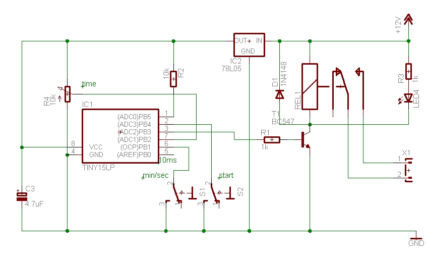
The time can be set using a potentiometer ranging from 1 minute to 1023 minutes, approximately 17 hours. A pushbutton initiates the timing process, activates a relay, and the timer will deactivate the relay once the set time has...
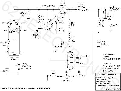
The following circuit illustrates the SciTech PS-3R Power Supply Circuit. Features include 13.8V DC output, 5 Amps surge capability, and a constant output of 3 Amps. Components include a transistor and others. The SciTech PS-3R Power Supply Circuit is designed...
Here a simple design for an attractive tone. They operate on a passive principle, ie without amplification. The circuit only weakened and therefore require no power. As can be seen, the circuit is built with two T-filters in the...
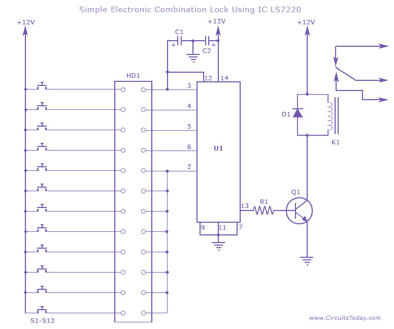
This circuit diagram illustrates a simple electronic combination lock utilizing the IC LS7220. It is designed to activate a relay for controlling any device (on & off) when a specific combination of four digits is entered. The circuit operates...
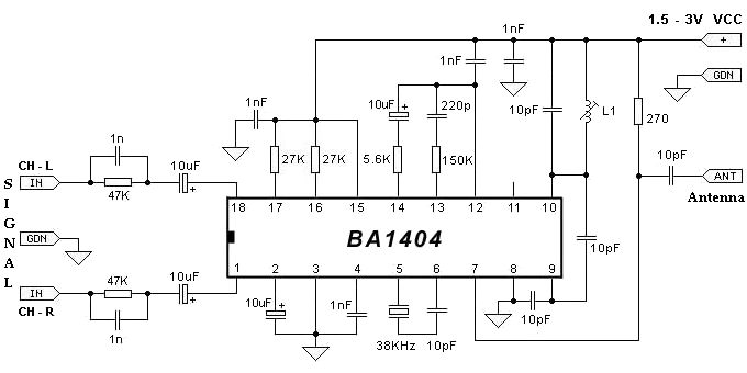
The BA1404 FM stereo modulator IC includes all the necessary components to design a simple, high-efficiency stereo transmitter circuit. It features a stereo modulator that generates composite stereo signals, an FM modulator for creating FM signals, and an RF...