
SciTech PS-3R Power Supply Circuit
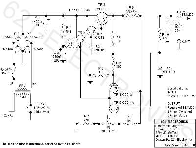
The SciTech PS-3R Power Supply Circuit is designed to provide a stable DC output of 13.8 volts, suitable for various electronic applications, particularly in powering devices that require regulated voltage. The power supply is capable of delivering a surge current of up to 5 Amps, which is beneficial for starting devices that may draw higher current momentarily. Under normal operating conditions, the circuit maintains a constant output current of 3 Amps, ensuring reliable performance for connected loads.
The circuit typically consists of a transformer, which steps down the AC voltage from the mains supply to a lower AC voltage. This AC voltage is then rectified using diodes to convert it into pulsating DC. A smoothing capacitor is used to filter the pulsating DC, providing a more stable output. The inclusion of a voltage regulator ensures that the output remains steady at 13.8V, even when the load varies.
Transistors within the circuit may be utilized for switching and amplification purposes, depending on the specific design requirements. Additional components such as resistors, capacitors, and possibly inductors may also be included to enhance performance, improve stability, and filter out noise.
Overall, the SciTech PS-3R Power Supply Circuit is engineered to deliver reliable power with specific features tailored for efficient operation in various electronic applications.The following circuit shows about SciTech PS-3R Power Supply Circuit. Features: 13.8vDC, 5 Amps Surge, 3 Amps Constant. Component: Transistor, .. 🔗 External reference
Related Circuits
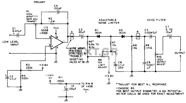
A preamplifier in the audio frequency range amplifies a noisy audio signal to drive a diode clipper. Suitable audio input levels would be in the 10-mV to 1-V range. The audio preamplifier circuit is designed to enhance weak audio signals, typically...
This instructable will demonstrate how to interpret various circuit diagrams and assemble circuits on a breadboard. The process of reading circuit diagrams involves understanding the symbols and connections that represent electronic components and their interrelations. Key components include resistors, capacitors,...
Normally the base of a cordless phone has an adaptor and the handset has Ni-Cd cells for its operation. The base unit becomes inoperative in case of power failure. In such conditions, it is better to provide a backup...
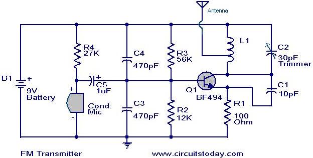
The MK484 AM receiver circuit is a simple design based on the MK484 AM receiver IC from Rapid Electronics Ltd. The MK484 is a monolithic integrated circuit that incorporates all necessary sections of an AM receiver, including an RF...
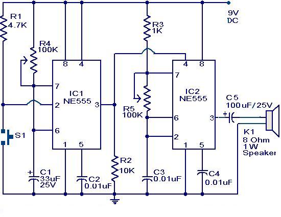
The primary component of this circuit is a doorbell utilizing two NE555 timer ICs. When the switch S1 is momentarily pressed, the speaker produces a bell sound, which is determined by the time period of the monostable multivibrator configured...
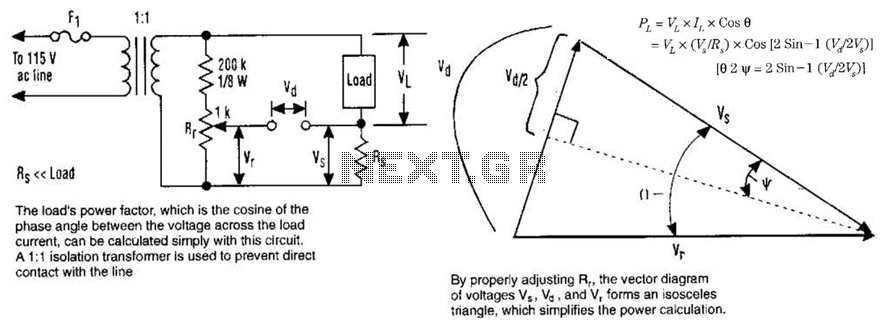
The load's power factor, defined as the cosine of the phase angle between the voltage across the load and the load current, can be calculated using this circuit. An isolation transformer with a 1:1 ratio is employed to prevent...