
Intelligent Solar Garden Light using an Arduino
The solar-powered garden light circuit utilizes a solar panel to harness energy during the day, charging the Ni-MH batteries. The power management is critical, as it ensures that the system operates efficiently and reliably. The choice of the Arduino Wee microcontroller is significant, as it provides the necessary processing power in a compact form factor while being compatible with the voltage levels provided by the battery configuration.
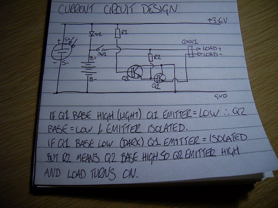
Transistor Q1 functions as a light sensor switch, controlling the operation of Q2, which drives the LED spotlights. The circuit is designed such that when sufficient ambient light is detected, Q1 is activated, grounding the base of Q2 and preventing the LEDs from illuminating. This design prevents unnecessary power consumption during daylight hours.
When darkness is detected, Q1 turns off, allowing the base of Q2 to receive a high signal through resistor R2, effectively turning on Q2. This action connects the emitter of Q2 to ground, completing the circuit for the LEDs. The gradual dimming feature is achieved through pulse-width modulation (PWM) controlled by the Arduino Wee. By varying the duty cycle, the brightness of the LEDs can be smoothly transitioned from off to fully on, enhancing the aesthetic appeal of the garden light.
The integration of sensor technology and microcontroller capabilities opens avenues for further enhancements, such as motion detection or ambient light adjustment, which could improve energy efficiency and user experience. The implementation of these features would require additional circuitry and programming but could significantly elevate the functionality of the solar garden light system.I bought a solar powered garden light. The solar panel charges the batteries and when it gets dark the lights (3x LEDs) turn on until it either gets lights again or the batteries run out. First, the batteries. The control box houses the batteries, which are three Ni-MH AA cells. They are 600mAh. (That`s not a typo six hundred). I swapped them out for three 1500mAh Ni-MH cells that I don`t use anymore (because they are only 1500mAh). I have a few ideas for sensors and transducers I want to add to the light, but I`ll start by adding a microcontroller. Step forward the Arduino Wee made by SparkFun Electronics. When light is falling on the solar cell, transistor Q1 is turned on and connects the base of transistor Q2 to ground.
This isolates the output of Q2 keeping the LED spotlights turned off. When it gets dark, Q1 is turned off, leaving the emitter isolated (floating). Assuming SW1 is turned on, the base of Q2 will be high due to R2. This will turn Q2 on and connect the emitter to ground. This completes the circuit for the LED spotlights and they turn on. So, the Arduino Wee is a 3. 3V device (the normal Arduino is 5V TTL). The battery is made of 3x 1. 2V cells giving 3. 6V total. The Wee can cope with the extra 0. 3V. I connected the Wee to the positive power rail after the switch and to the negative rail on the battery compartment. Then I unsoldered R1 and connected digital pin 3 to the base of transistor Q1, and the analogue input A0 to the positive rail of the solar panel.
The Wee can now control the LED spotlights and knows if it`s light or dark. As there`s intelligence in the solar garden light now, why just turn the lights on immediately when it gets dark That`s not very sophisticated is it Slowly turning the light on and getting brighter until it`s fully on, looks sooooo much better. You can see on the scope the pulses. It`s showing about a 50:50 mark space ratio, so the light is at 50% brightness. It takes about two seconds to go from fully off to fully on. I think it looks cool. 🔗 External reference
Related Circuits
Telephone ringer utilizing 556 dual timers. This circuit generates ringing tones resembling those of a telephone by employing modulated rectangular waves of varying time periods. The telephone ringer circuit employs two 556 dual timer ICs configured to generate modulated rectangular...
As a cyclist, there is a constant search for methods to enhance visibility during nighttime rides. The concept of the `NITE-RIDER` was developed to create a distinctive and attention-grabbing rear light for bicycles. This design features nine extra-bright LEDs...
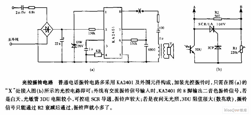
The average telephone ring circuit consists of the KA2401 integrated circuit and its associated peripheral components. To integrate a light-operated ring circuit, connect the designated part X in the provided diagram (picture a) to the light-operated circuit shown in...

A small servo tester for modeling can be very useful in various situations for those who frequently work with servos. The primary function of a servo tester is to produce a pulsing signal with a positive pulse width that...
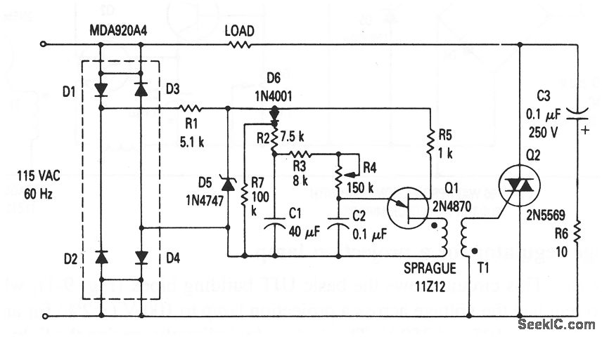
This circuit illustrates the fundamental UJT building block, utilized in a light dimmer with soft-start functionality. It gradually applies current to the light, effectively minimizing high surges (high inrush current) that typically occur in cold-filament light dimmers, which can...
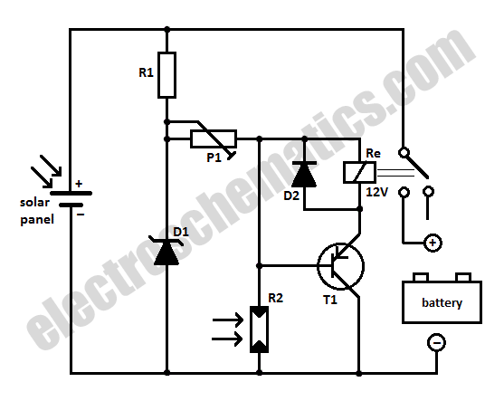
When charging a battery during the day using a solar panel, there is a risk of the battery partially discharging through the panel after sunset. This solar panel power switch circuit eliminates the need for a diode by utilizing...