
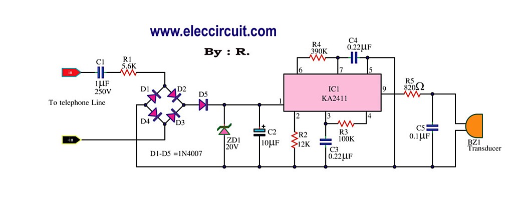
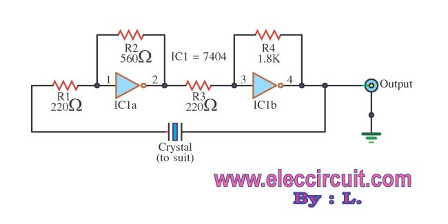
Telephone Ringer using 556 dual timers
The telephone ringer circuit employs two 556 dual timer ICs configured to generate modulated rectangular waveforms. The 556 timer is a versatile integrated circuit that combines two 555 timer circuits, allowing for a compact design while providing multiple timing functions. In this application, the timers are set up in astable mode to create square wave outputs, which can be adjusted by varying the resistor and capacitor values in the timing network.
The first timer generates a base frequency that simulates the ringing tone of a traditional telephone. This frequency can be adjusted by changing the values of the resistors and capacitors connected to the timing pins of the 556 IC. The output from this timer is then fed into the second 556 timer, which modulates the frequency to create a more realistic ringing effect. By varying the duty cycle and frequency of the output from the second timer, different ringing patterns can be produced, mimicking the tones of various telephone systems.
The circuit can be powered by a standard DC power supply, typically between 5V to 15V, depending on the specifications of the 556 timers used. The output of the second timer can be connected to a small speaker or a piezoelectric buzzer, which will convert the electrical signals into audible ringing tones.
Additional components such as diodes may be included to protect the circuit from voltage spikes, while capacitors can be used for filtering and stability. Overall, this telephone ringer circuit provides an effective solution for simulating traditional telephone ringing tones in various electronic projects.Telephone Ringer using 556 dual timers. Using modulated rectangular waves of different time periods, The circuit presented here produces ringing tones similar to those produced by a telephone. The. 🔗 External reference
Related Circuits
This circuit detects the dial tone from a telephone line and decodes the keypad pressed on the remote telephone. The dial tone heard when picking up the phone is known as Dual Tone Multi-Frequency (DTMF). The term is derived...
The simplest method of detecting metal is through a beat frequency oscillator. The circuit consists of two balanced oscillators: one serves as the detector element while the other provides a reference signal. The reference oscillator frequency is set to...
This circuit is designed to generate a loud ringing tone for an electricity bell in older telephones. It serves as a replacement for the original ringer, which may be lost, eliminating the need for a new phone. The circuit...
The circuit operates using binary signal statuses of "1" and "0". It also incorporates a frequency generator. The circuit described utilizes a binary signaling system, which is fundamental in digital electronics. The binary states "1" and "0" represent the two...

A simple battery charger circuit with reverse polarity indication is presented. The circuit utilizes the L200 integrated circuit, which is a five-pin variable voltage regulator. It can be powered by DC voltage from either a bridge rectifier or a...
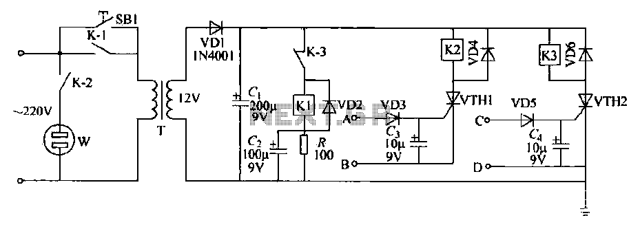
This schematic circuit features two alarm outputs controlled by a timer using thyristors. The system can be turned on or off and will shut down after the power supply is interrupted. It employs a transformer on the primary side...