
servo tester using 4538
The servo tester circuit utilizing the 4538 integrated circuit is designed to provide reliable control of servo motors by generating precise pulse-width modulation (PWM) signals. The circuit architecture consists of a 4538 dual astable multivibrator, which is configured to produce a continuous square wave output. The frequency and duty cycle of this output are adjustable through the use of a potentiometer (P1) and fixed resistors (R1) in conjunction with a timing capacitor (C1).
In this configuration, the output pulse width is directly influenced by the resistance values selected. By varying the resistance of the potentiometer, the user can fine-tune the pulse width to achieve the desired servo position, allowing for precise control over the servo's movement. The output from the first multivibrator (IC1a) triggers the second multivibrator (IC1b), creating a feedback loop that maintains the oscillation of the signal. The calculated total period of the output signal ensures that the servo tester operates within the specified frequency range, making it suitable for a variety of servo applications.
The simplicity of the circuit design, requiring minimal external components, contributes to its effectiveness and ease of use. This makes the servo tester an invaluable tool for hobbyists and professionals alike, enabling them to test and calibrate servo motors efficiently. Additionally, the use of the 4538 IC, with its dual multivibrator capability, provides a unique alternative to more commonly used timer ICs, showcasing versatility in circuit design and functionality.There are times when a small servo tester for modeling comes in very useful. Everybody who regularly works with servos will know several instances when such a servo tester will come in handy. The function of a servo tester is to generate a pulsing signal where the width of the positive pulse can be varied between 1 and 2 ms.
This pulse-width deter mines the position the servo should move to. The signal has to repeat itself continuously, with a frequency of about 40 to 60 Hz. These circuits often use an NE555 or one of its derivatives to generate the pulses. This time we have used a 4538 for variety. This IC contains two astable multi-vibrators. You can see from the circuit diagram that not many other components are required besides the 4538. The astable multi-vibrator in a 4538 can be started in two ways. When input I 0 (pin 5 or 11) is high, a rising edge on input I 1 (pin 4 or 12) is the start signal to generate a pulse. The pulse-width at the output of IC1a is equal to (R1+P1)G—C1. This means that when potentiometer P1 is turned to its minimum resistance, the pulse-width will be 10 k G— 100 n = 1 ms.
When P1 is set to maximum (10 k), the pulse-width becomes 20 k G— 100 n = 2 ms. At the end of this pulse inverting output Q generates a rising edge. This edge triggers IC1. B, which then generates a pulse. The pulse-width here is 82 k G— 220 n 18 ms. At the end of this pulse the Q output will also generate a rising edge. This in turn makes IC1. A generate a pulse again. This completes the circle. Depending on P1, the total period is between 19 and 20 ms. This corresponds to a frequency of about 50 to 53 Hz and is therefore well within the permitted frequency range. 🔗 External reference
Related Circuits

A LAN tester circuit diagram is presented in two designs. The first design utilizes a timer IC 555 and a decade counter 4017. The second design employs a microcontroller ATtiny2313. The first design of the LAN tester circuit incorporates the...
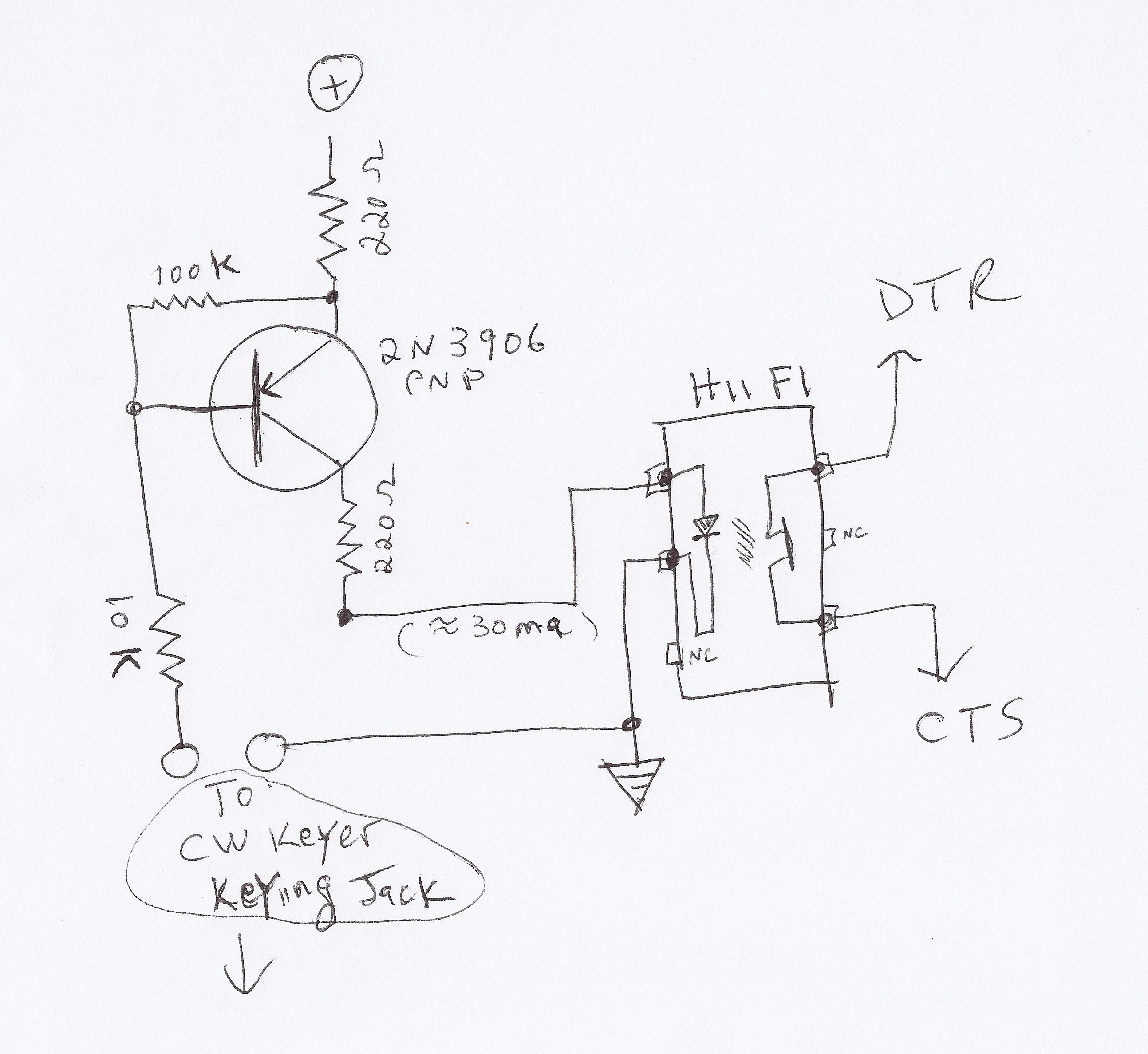
This video demonstrates how to initiate multiple instances of QsoNet's Dahdidah CW Software Keyer using FABULATECH's Virtual Serial Port Splitter. Four separate... The QsoNet Dahdidah CW Software Keyer is a sophisticated tool designed for amateur radio operators, allowing them to...

Using just two NAND or inverter gates, it is possible to build a D-type (or toggle) flip-flop with a push-button input. At power-up, the output of gate N2 is at a logical 1, ensuring that transistor T2 is switched...

The telephone ring generator shown below generates the needed high voltage from a simple switching mode power supply (SMPS) which employs a CMOS Schmitt Trigger square wave oscillator, 10 mH inductor, high voltage switching transistor (TIP47 or other high...
A guitar to MIDI interface was designed to serve as an interface between guitar playing and MIDI control of external hardware and software. This document describes the details of the design, experimentation, implementation, and final outcome of the project....
The title contains numerous words because this instructable integrates various concepts from multiple sources. The primary idea originated from Robomaniac's Desktop Energy Seed Lamp, combined with Witch's Growing Plants with LED Lights instructable and various wick gardening planters. The...
Warning: include(partials/cookie-banner.php): Failed to open stream: Permission denied in /var/www/html/nextgr/view-circuit.php on line 713
Warning: include(): Failed opening 'partials/cookie-banner.php' for inclusion (include_path='.:/usr/share/php') in /var/www/html/nextgr/view-circuit.php on line 713