
Interface

The Si7135 integrated circuit is designed for interfacing with microprocessors such as the 8080/8048 and MC6800 families, which utilize 8-bit word architectures. This interfacing requires careful multiplexing of signals, specifically polarity, overrange, and underrange conditions, onto the fifth digit of the word. This allows the microprocessor to effectively manage and interpret the output from the Si7135, ensuring that data integrity is maintained during the conversion process.
The microprocessor has the capability to control the analog-to-digital converter (ADC) by sending commands to initiate and hold measurements. This functionality is crucial for applications that require precise timing and control over data acquisition. The Si7135 operates with a power supply range of ±5 V, which is standard for many digital circuits. However, in applications where a negative voltage supply is not readily available, an alternative solution is necessary.
To generate a negative supply, a circuit can be implemented using two capacitors in conjunction with a low-cost voltage converter IC, such as the Si7660 or Si7661. This setup allows for the generation of the required negative voltage from a positive supply, enabling the Si7135 to function correctly even in power supply configurations that do not provide a negative rail. The implementation of this solution is depicted in Fig. 18-2c, illustrating the simplicity and effectiveness of using capacitors and a voltage converter IC to meet the power requirements of the Si7135 in various applications.Circuits to interlace the Si7135 directly with two popular microprocessors are shown in Figs. 18-2a and b. The 8080/8048 and the MC6800 families with 8-bit words need to have polarity, overrange, and underrange multiplexed onto the digit 5 word. In each case, the microprocessor can instruct the ADC when to begin a measurement and when to hold this measurement.
The Si7135 is designed to work from ±5 V supplies. However, if a negative supply is not available, it can be generated using 2 capacitors, and an inexpensive Si7660 or Si7661 IC, as shown in Fig. 18-2c.
Related Circuits
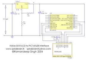
This project demonstrates the interfacing and operation of the Nokia 3310 LCD using the PIC16F628 microcontroller. The programming is executed in Hi-Tech C, with the character table incorporated within the source code. The Nokia LCD features a resolution of...
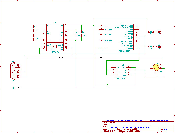
This circuit represents a Dive computer interface for RS232. Uses the MAX232A. The described circuit serves as an interface for a dive computer utilizing the RS232 communication protocol, incorporating the MAX232A integrated circuit. The MAX232A is a dual voltage-level converter...
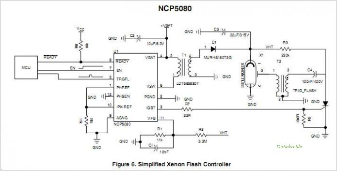
The NCP5810D is a dual-output DC/DC converter capable of generating both positive and negative voltages. This device is optimized for powering modules such as AMOLED display drivers, where high output voltage accuracy, regulation, signal integrity, and compact design are...
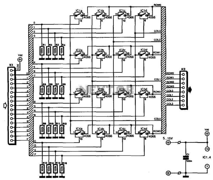
Keyboards can be classified into two categories based on the connection method of the switches: those with a common connection and those arranged in a matrix. The matrix type offers the significant advantage of minimizing the number of connections,...
The project concept originated nearly two years ago during research for a new lighting board for a small theater. The existing board was nearly twenty years old and in dire need of replacement. However, the costs associated with purchasing...
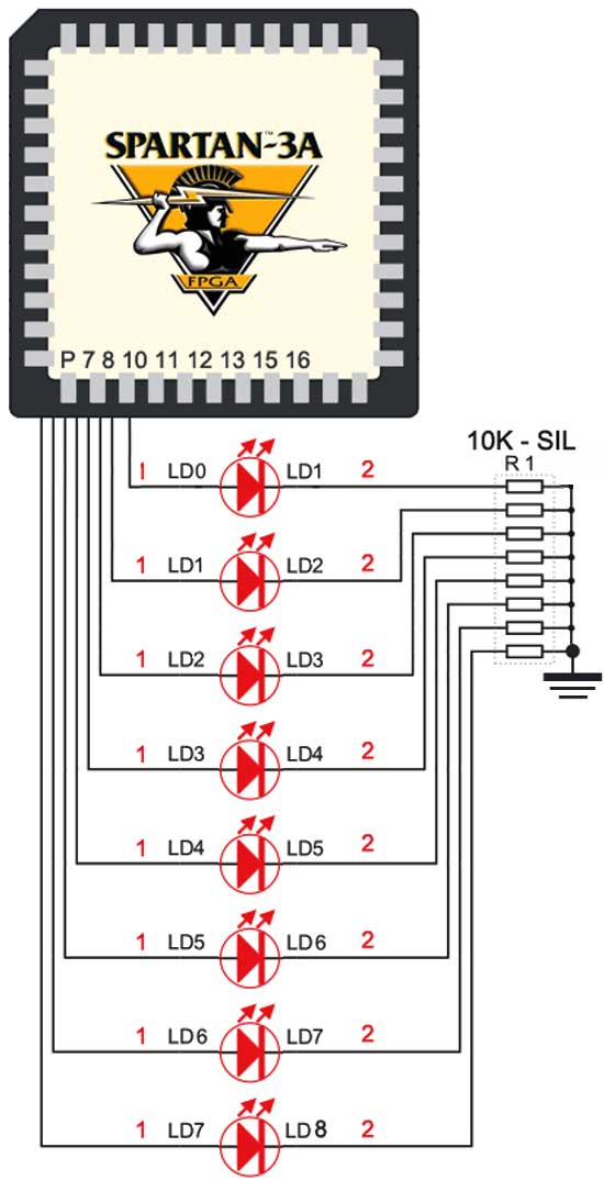
The Spartan-3an board features eight LEDs connected to FPGA I/O pins. The cathode of each LED is connected to ground through a 330-ohm resistor. To illuminate a specific LED, the corresponding FPGA control signal must be set to High. The...