
how to interface led with spartan 3an
The Spartan-3an board is designed for integration with various digital systems, leveraging its FPGA capabilities to control the eight LEDs. Each LED serves as an output indicator, providing visual feedback based on the state of the FPGA control signals.
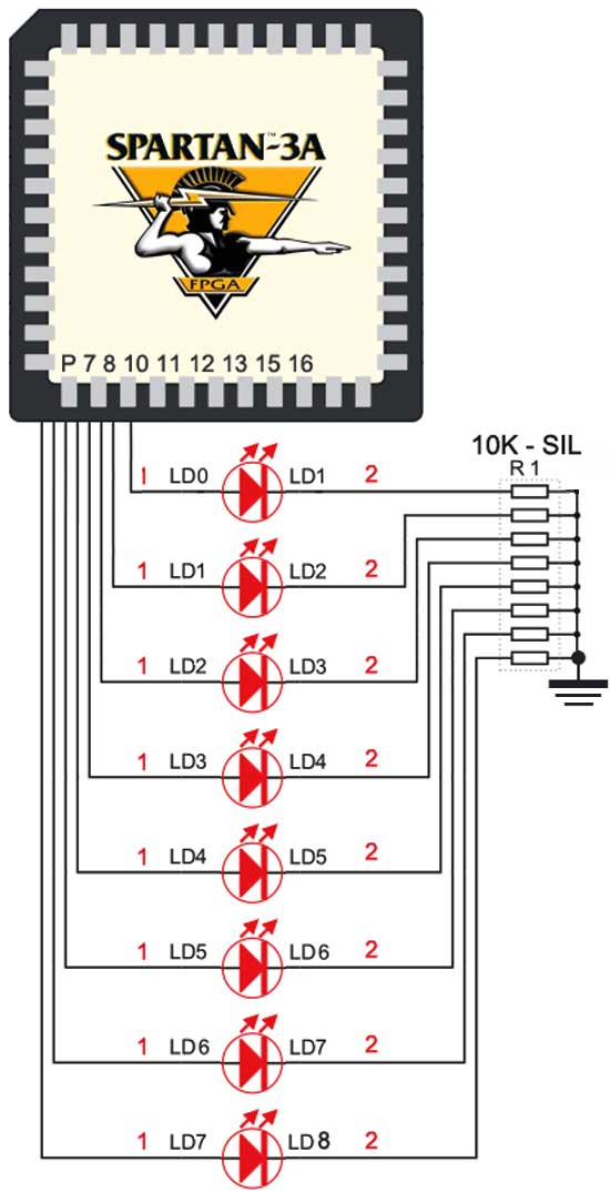
The configuration involves connecting the anodes of the LEDs to designated I/O pins on the FPGA. Each LED's cathode is linked to ground through a 330-ohm resistor, which limits the current flowing through the LED, thereby preventing damage from excessive current. The choice of a 330-ohm resistor is typical for standard 5V supply LEDs, ensuring adequate brightness while maintaining safe operating conditions.
To activate an LED, the associated I/O pin must be driven to a High state (logic level 1), which allows current to flow from the power supply through the LED and the resistor to ground. Conversely, driving the I/O pin to a Low state (logic level 0) turns the LED off, as no current flows through the circuit.
This setup is commonly utilized in educational and prototyping environments, allowing users to experiment with digital logic and FPGA programming. The straightforward nature of the LED control mechanism makes it an excellent starting point for understanding more complex digital systems and FPGA applications.The Spartan-3an board has eight LED Connected with FPGA I/O pins (details tabulated below). The cathode of each LED connects to ground via a 330 © resistor. To light an individual LED, drive the associated FPGA control signal to High. 🔗 External reference
Related Circuits

The circuit depicted in Figure 3-92 employs a dual-phase sequence protection relay for sensing. When the power supply exhibits a positive phase sequence (U, V, W), the relay KA is activated. If the power supply maintains the correct phase...
In the circuit below, 60 individual LEDs indicate the minutes of a clock, while 12 LEDs represent the hours. The power supply and timing circuitry are similar to those described in the previous 28 LED clock circuit. The minute...

A transistor optocoupler interface circuit, as described in section 15.1.6, has been implemented. This circuit serves as a transistor interface with other circuits. The transistor optocoupler interface circuit utilizes a light-emitting diode (LED) and a phototransistor to achieve electrical isolation...
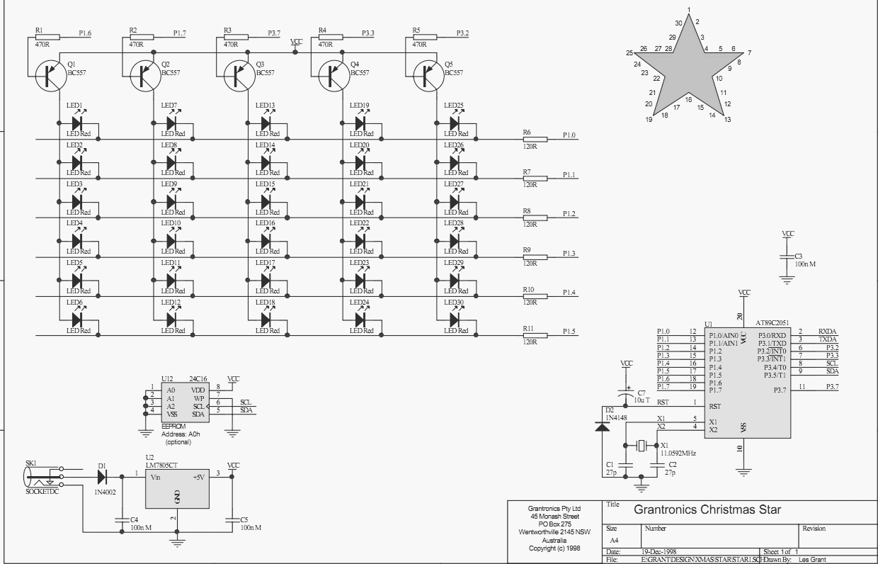
Using a PC parallel port to control external devices is a popular approach these days but I certainly couldn’t afford to tie up a PC for the few weeks leading up to Christmas just to flash a few LEDs!...

A simple 741 amplifier is utilized as a current-to-voltage converter, with an LED serving as the current source. The output voltage is proportional to the incident light. The junction is biased solely by the difference between the output summing...

This circuit features a LED sequencer/chaser utilizing the CD4017 and NE555 integrated circuits (ICs). The CD4017 is a CMOS counter IC with 16 pins, providing 10 outputs based on the clock pulses received at its clock input, pin 14....
Warning: include(partials/cookie-banner.php): Failed to open stream: Permission denied in /var/www/html/nextgr/view-circuit.php on line 713
Warning: include(): Failed opening 'partials/cookie-banner.php' for inclusion (include_path='.:/usr/share/php') in /var/www/html/nextgr/view-circuit.php on line 713