
Interface circuit fsk modulation and power lines
The circuit operates by generating two distinct frequencies for the modulation of control signals. The 556 timer IC is configured in an astable mode, which allows it to oscillate continuously, producing square waves at the designated frequencies of 100 kHz and 90 kHz. The resistors and capacitors are carefully selected to determine the frequency of oscillation, ensuring that the output signals are stable and within the desired frequency range.
The analog switch CC4066 is employed to control the flow of the serial coded modulated signal, allowing for dynamic control over the transmission process. This capability is essential for applications that require precise signal management.
The amplifiers VT1 and VT2 serve to boost the power of the generated signals, making them suitable for transmission over the power line. The use of transformers T, CX1, and CX2 provides necessary high-voltage isolation, ensuring that the control signals do not interfere with the main power line and are safely transmitted without risk of electrical shock or damage to other components.
The frequency selection circuit formed by T1 and C8 plays a crucial role in filtering and selecting the appropriate frequencies for transmission, optimizing the circuit's performance in various operational conditions. This setup allows the circuit to effectively utilize power line communication techniques, making it suitable for remote control applications and other scenarios where signal transmission over existing power infrastructure is required.
Overall, the design emphasizes reliability and efficiency, ensuring that control signals can be transmitted effectively while maintaining high-voltage safety standards. Circuit serial coded modulated control signal, amplify, and transmit high voltage isolation. 556 time base circuit and R1, R2, C1 and R3, R4, C2 form two astable multivibrator, 100kHz and 90kHz to generate two signals. Serial control signal to the analog switch CC4066 control. 5 556 feet high when the output of the resonant harmonic 100kHz to VT1 amplifier and T, CX1, CX2 isolation, coupled to the power line. T1, C8 composition selected frequency circuits, T, CX1, CX2 composed of high-voltage isolation circuit.
The serial signal is low, 556 feet 9 output harmonic 90kHz to VT2, by resonance amplification and T, CX1, CX2 isolation coupled to the power line. This circuit can use power line carrier channel to transmit control signals.
Related Circuits

A GdS cell serves as one leg of a bridge circuit. Potentiometer R6 in another leg establishes the trip point. Potentiometer R5 allows for hysteresis adjustment to prevent chattering or hunting of the relay. The light level must increase...
To configure the amplifier, set resistor R1 to its maximum value and resistor R12 to zero. After this adjustment, power on the amplifier. Adjust R1 until the measured output offset is between 30 mV and 100 mV. Once this...
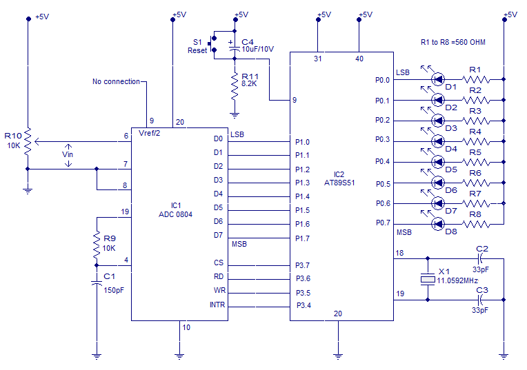
Interfacing ADC to 8051 microcontroller. ADC0804 is interfaced to microcontroller AT89S51. Complete circuit, theory and program in assembly language. The interfacing of an Analog-to-Digital Converter (ADC) with a microcontroller is a critical aspect of embedded systems design, particularly when analog...
This circuit is a compact +5V power supply that is beneficial for digital electronics experimentation. Inexpensive wall transformers with variable output voltage can be found at electronics shops and supermarkets. While these transformers are readily available, their voltage regulation...
With this circuit we can change the brightness of lamb, with a only key of touch. The key of touch is connected in the circuit, center of which is a special completed IC1, which is the S566B of SIEMENS....
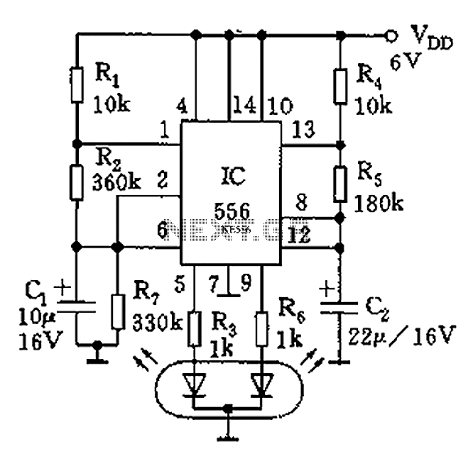
The circuit features a dual-core 556 timer IC and a light-emitting diode (LED) tube. The left half of the IC (556 1/2) comprises resistors R1, R2, capacitor C1, etc., generating a frequency of approximately 2 Hz in a multivibrator...