
Precision Dark-Activated Switch With Hysteresis Circuit

The described circuit utilizes a GdS (Gallium Sulfide) light sensor, which is sensitive to changes in light levels. In this configuration, the GdS cell is integrated into a bridge circuit, which typically consists of four resistive elements arranged in a diamond shape. The bridge circuit is designed to measure the imbalance created by changes in light intensity, which affects the resistance of the GdS cell. This imbalance generates a voltage difference across the bridge, which can be monitored.
Potentiometer R6, positioned in one leg of the bridge, is used to set a specific trip point. This trip point determines the threshold at which the circuit responds to changes in light intensity. By adjusting R6, the user can define the sensitivity of the circuit, allowing it to activate or deactivate based on the desired light level.
Potentiometer R5 is incorporated into the circuit to provide hysteresis. Hysteresis is a critical feature that helps stabilize the operation of the relay by preventing rapid on-off cycling, often referred to as chattering or hunting. This is achieved by introducing a delay in the turn-off point of the circuit, ensuring that the light level must increase significantly beyond the trip point before the transistor 2N3904 turns off. This design consideration is crucial in applications where stable operation is necessary, such as in lighting control systems or automatic light sensors.
The 2N3904 transistor functions as a switching element in this circuit. When the light level falls below the defined trip point, the transistor is activated, allowing current to flow through the relay, which in turn can control larger loads. Conversely, when the light level rises sufficiently, the transistor turns off, deactivating the relay and stopping the current flow. This behavior ensures that the circuit responds effectively to changes in ambient light conditions while maintaining reliable operation. A GdS cell is one leg of a bridge circuit. Potentiometer R6 iri another leg sets the trip point. Potentiometer R5 provides hysteresis adjustment to prevent chattering or hunting of the relay. The light level has to increase noticeably before the 2N3904 turns off and the circuit deactivates. 🔗 External reference
Related Circuits
The 555 timer is recognized as one of the most versatile and widely used integrated circuits globally. One of its potential applications is as a simple inverting Schmitt trigger. The 555 timer can be configured in various modes, including monostable,...
This automatic NiCd charger for 9V NiCd batteries utilizes the properties of a 555 timer and is straightforward to construct. The charger is designed to automatically maintain a full charge on the battery, allowing it to remain connected for...
The circuit allows up to eight participants, each assigned a unique number from 1 to 8. The display indicates the number of the contestant who presses their button before the others. Simultaneously, a buzzer sounds. Both the display and...
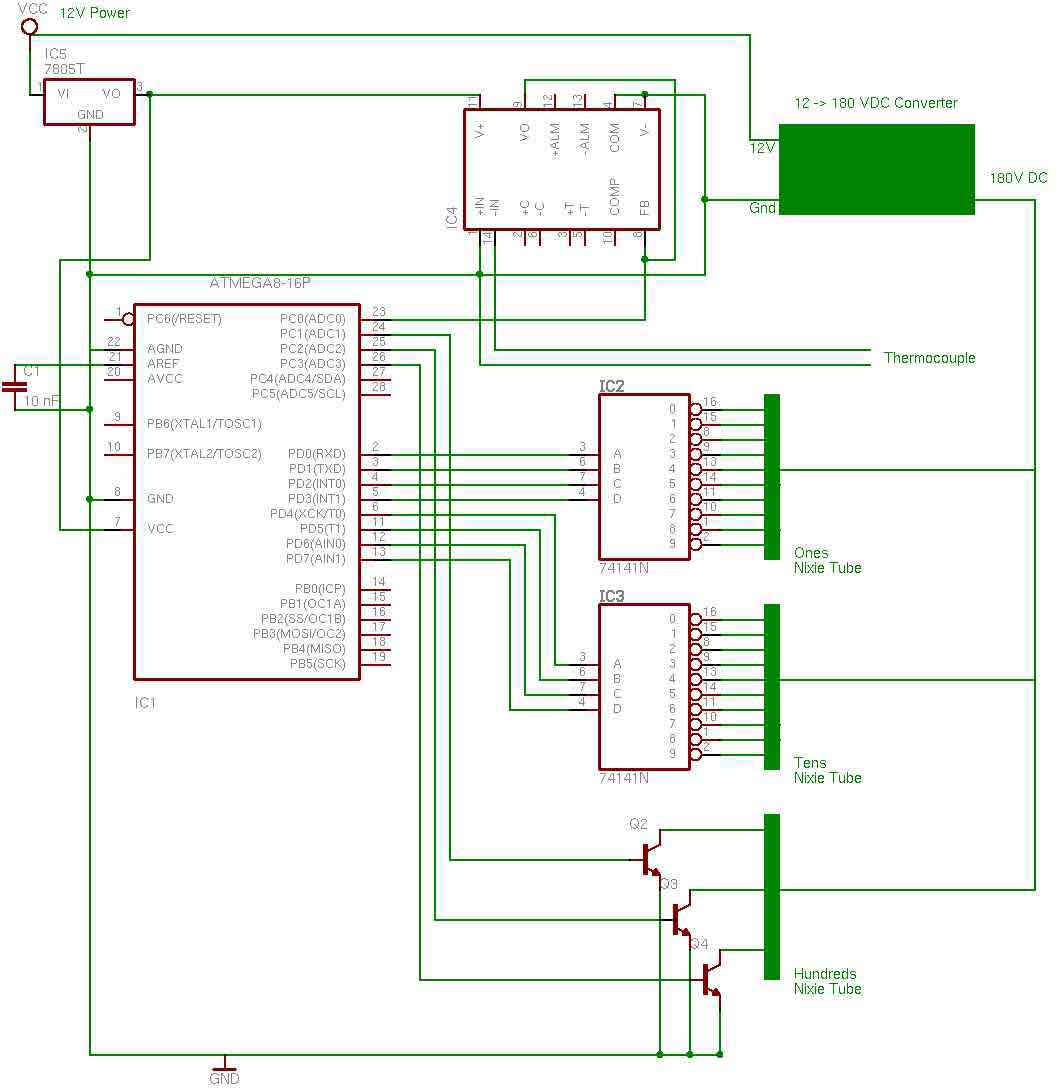
the entire circuit is comprised of integrated circuits. This makes for some easy organization when it goes to the circuit board for soldering. In addition, I used only 3 of the pins on the 3rd nixie tube for the...

A South African company has developed a 5-kilowatt Fuel Free Generator and discovered that the longevity of the batteries is significantly affected by the process. There are various types of batteries available for testing, including different lead-acid batteries, gel...
The power supply has been simplified. Power transformers and rectifiers have been omitted, and some components from the MOSFET voltage regulator circuits have been removed, including 1N5242 zener diodes between the source and gate and 10k resistors in series...
Warning: include(partials/cookie-banner.php): Failed to open stream: Permission denied in /var/www/html/nextgr/view-circuit.php on line 713
Warning: include(): Failed opening 'partials/cookie-banner.php' for inclusion (include_path='.:/usr/share/php') in /var/www/html/nextgr/view-circuit.php on line 713