
interface gps with avr
The GPS modem serves as a crucial component in navigation systems, allowing users to determine their precise location by processing satellite signals. The integration with the ATmega16 microcontroller facilitates the extraction and manipulation of location data, enabling applications ranging from simple navigation aids to complex geographic information systems. The use of the MAX232 IC is essential for ensuring compatibility between the TTL logic levels of the microcontroller and the RS232 levels required for communication with other devices, such as PCs.
The circuit design involves careful consideration of signal integrity and power management, particularly when interfacing with the LCD display. The 16x2 LCD is chosen for its simplicity and versatility in displaying alphanumeric characters, making it suitable for real-time feedback in navigation applications. The ATmega16's architecture provides a robust platform for processing the incoming GPS data and controlling the display output, allowing for efficient data handling and user interaction.
In summary, the combination of the GPS modem, ATmega16 microcontroller, MAX232 level shifter, and 16x2 LCD display forms a comprehensive system capable of receiving, processing, and displaying location data, illustrating the practical application of electronic components in modern navigation solutions.GPS modem is a device which receives signals from satellite and provides information about latitude, longitude, altitude, time etc. The GPS navigator is more famous in mobiles to track the road maps. The GPS modem has an antenna which receives the satellite signals and transfers them to the modem. The modem in turn converts the data into useful information and sends the output in serial RS232 logic level format. The information about latitude, longitude etc is sent continuously and accompanied by an identifier string. This article shows how to interface the GPS modem with ATmega16 and extract the location (latitude and longitude) from the GPGGA string and display it on LCD.
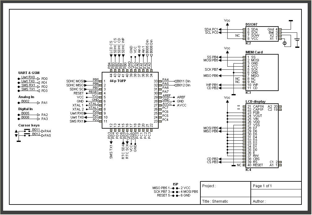
The connection of GPS modem with AVR microcontroller (ATmega 16) is shown in the circuit diagram. The ground pin of max 232 and serial o/p of GPS modem is made common. Pin2 of MAX232 is connected to pin 3 of GPS modem and pin 3 of max 232 is connected to pin 2 of modem. This type of connection is called a serial cross cable. The following is an example of the output string from the GPS module with its explanation. This output strings contains information about latitude, longitude, time etc and will always start with $GPGGA.
Refer NMEA Standards for more details on string formats. The MAX232 IC is used to convert the TTL/CMOS logic levels to RS232 logic levels during serial communication of microcontrollers with PC. The controller operates at TTL logic level (0-5V) whereas the serial communication in PC works. LCD (Liquid Crystal Display) screen is an electronic display module and find a wide range of applications.
A 16x2 LCD display is very basic module and is very commonly used in various devices and circuits. These modules are preferred over seven segments. ATmega16 is an 8-bit high performance microcontroller of Atmel`s Mega AVR family with low power consumption. Atmega16 is based on enhanced RISC (Reduced Instruction Set Computing) architecture with 131 powerful instructions.
Most of the instructions execute in one machin. 🔗 External reference
Related Circuits
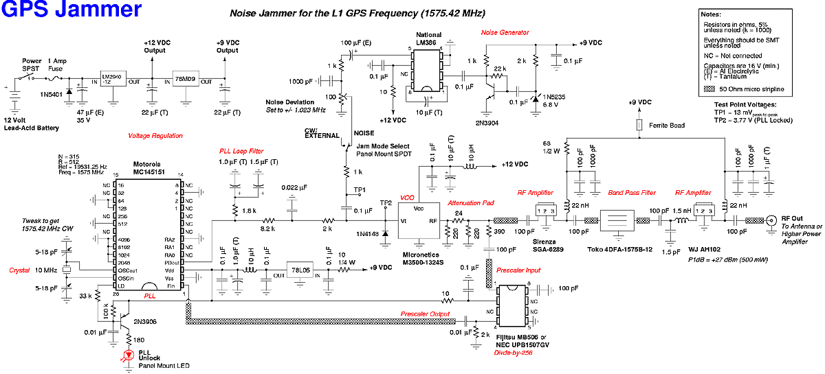
A low cost device to temporarily disable the reception of the civilian coarse acquisition (C/A) code used for the standard positioning service (SPS) on the Global Positioning System (GPS/NAVSTAR) L1 frequency of 1575.42 MHz. This is accomplished by transmitting...
If this picture above looks a lot like the Pretty Good LC Meter also on this web site, that's because it's the same meter, but with some significant improvements. At this point, it's a good idea to read the...
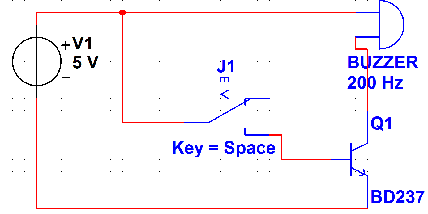
A PB-12N23PW-05Q buzzer is being used with an ATmega 162 microcontroller. Direct connection to the microcontroller pin is not feasible due to the maximum sourcing capability of 20 mA as stated in the ATmega 162 datasheet, while the buzzer...
AVRtools features an intuitive graphical user interface and utilizes predefined function blocks. It provides a wide array of basic functions, including timers, counters, logic operations, and analog signal processing. Additionally, it includes function blocks for sending SMS messages over...
LED displays consist of arrays of Light Emitting Diodes (LEDs) arranged in various shapes to convey specific information. The operation of LED displays is similar to that of standard LEDs, requiring straightforward connections when sufficient microcontroller pins are available....
The IIC bus line is a type of communication protocol that facilitates the transmission of data between devices. It is characterized by its simplicity in construction and wiring, making it suitable for various high-performance applications. The operating system, particularly...