
Variable GPS Jammer
Technical Description
This will be a brief description of each of the major sections which compromise the entire jammer device. Refer to the included schematic diagram as you read along. You should also refer to the component's datasheets for even more detailed information.
Phase Locked Loop
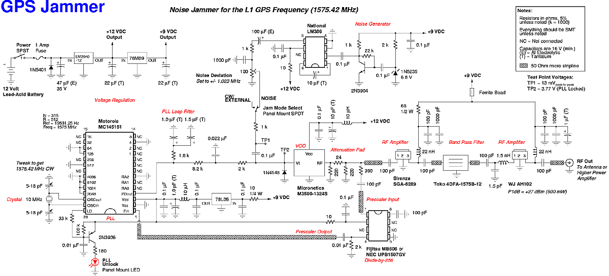
The jammer's main oscillator components consist of a Motorola MC145151 phase-locked loop (PLL) frequency synthesizer chip, a Micronetics M3500-1324S voltage controlled oscillator (VCO) module and a Fujitsu MB506 divide-by-256 prescaler chip. The VCO feeds a portion of its radio frequency (RF) output signal into the prescaler chip, where it is divided by 256. A 1575 MHz signal would be turned into a 6.15234375 MHz signal. This is then fed into one side of the PLL chip. The other side of the PLL is fed with a reference frequency which is derived from a 10 MHz quartz crystal. This crystal reference frequency is divided down 512 times by the PLL to reach 19531.25 Hz. The 6.15234375 MHz prescaler output frequency is also further divided down 315 times by the PLL chip for a final frequency of 19531.25 Hz. This will be the new PLL internal reference frequency. That big bad 1575 MHz microwave signal now looks like a simple audio frequency to the PLL chip and the supporting components. The PLL chip internally compares the phase of the 19531.25 Hz VCO side signal to the phase of the 19531.25 Hz crystal side signal. The PLL chip outputs high or low voltage pulses depending on whether the crystal signal is leading or lagging in phase with the VCO signal. These pulses are then filtered and dampened into a pure DC control signal via a simple passive loop filter. This cleaned up signal is then connected to the VCO's voltage tune control input. When everything is working properly, the VCO's output frequency is locked to whatever frequency you programmed into the PLL chip, 1575 MHz in this case. It will stay on that frequency even through dramatic temperature changes, a problem that a non-PLL VCO would have. If the PLL is not working properly, the red "PLL Unlock" LED will be lit. The VCO's +7 dBm (5 milliwatts) RF output is first slightly attenuated (4 dB) and tapped for the MB506 prescaler input. It then passes through to the RF amplifier stages and band pass filter. The first RF amplifier is a Sirenza Microdevices SGA-6289. It provides about 13 dB of gain to overcome the losses from the resistive attenuation pad. It also shows a good 50 Ohm termination for the VCO RF output and even helps to drive the final RF amplifier. The GPS band pass filter is a 2-pole Toko 4DFA-1575B-12 ceramic dielectric filter from Digi-Key, part number TKS2609CT-ND. This part is optional, but helps clean up the RF spectrum before further amplification. The filter's insertion loss is around 2 dB. The final RF amplifier is a WJ Communications AH102. It provides another 13 dB of gain, with a higher P1dB compression point of around +27 dBm (500 mW). The AH102 draws the most current of any part, and is not really necessary if you're aiming for a low range, low current, battery operated device.
Voltage Regulation
Voltage input regulation and filtering is done using standard voltage regulator ICs. A LM2940CT-12 12 Volt, 1 Amp low dropout voltage regulator is used to regulate the main 12 Volt power line. Standard 78xx series regulators are used from there on to provide both the 9 and 5 Volt lines. A simple diode/fuse polarity protection scheme is also provided on the battery input. The use of an automatic reset fuse is highly recommended. You can power the jammer off a common 12 Volt rechargeable battery. The 12 Volt, 4.5 Amp-hour, lead-acid battery from Radio Shack, part number 23-289, is a good choice. Old car batteries, strings of 6 Volt lantern batteries or even solar panels will also work. Current draw for the completed jammer will be around 300 milliamps.
Antenna
A radiating antenna is not shown in the schematic diagram and one will need to be purchased or constructed for proper operation. There are numerous commercial GPS receiving antennas which will work fine for this low power transmitting application. Some of the best pre-made or easily assembled microwave antennas can be purchased directly from Ramsey Electronics. The Ramsey DA25 broadband discone antenna is recommended for omni-directional (transmit in a circle) radiating applications. The LPY2 log periodic Yagi antenna can be used for directional (transmit in a straight line) radiating applications. Using a directional antenna will give you a slight increase in overall transmitted RF power, which increases the jammer's range, and can also be used to shield your own GPS receiver from being jammed (i.e. point it at the enemy). Dielectric GPS patch antenna elements may also be purchased from Digi-Key. Toko DAK series elements, Digi-Key part number TK5150-ND, are perfect for surface mounting directly to the circuit board. They will require a plastic radome to slightly lower their resonant frequency. The small antenna element size is also perfect for hidden or portable operations. Due to a quirk with using low cost, easy to obtain components, you'll need to tweak two loading capacitors on the reference crystal. This is unusual, but necessary to move the signal from the default 1575 MHz to the more appropriate 1575.42 MHz (+/- a few hundred Hertz). This is a very important and delicate procedure, and you'll need a frequency counter to accomplish it.A low cost device to temporarily disable the reception of the civilian coarse acquisition (C/A) code used for the standard positioning service (SPS) on the Global Positioning System (GPS/NAVSTAR) L1 frequency of 1575.42 MHz. This is accomplished by transmitting a narrowband Gaussian noise signal, with a deviation of +/- 1.023 MHz, on the L1 GPS frequency itself.
This technique is a little more complicated than a simple continuous wave (CW) jammer, but tends to be more effective (i.e. harder to filter) against spread spectrum based radio receivers. This device will have no effect on the precise positioning service (PPS) which is transmitted on the GPS L2 frequency of 1227.6 MHz and little effect on the P-code which is also carried on the L1 frequency.
There may be a problem if your particular GPS receiver needs to acquire the P(Y)-code through the C/A-code before proper operation. This device will also not work against the new upcoming GPS L5 frequency of 1176.45 MHz or the Russian GLONASS or European Galileo systems. It can be adapted to jam the new civilian C/A-code signal which is going to also be transmitted on the GPS L2 frequency.
That said, it will work against the majority of consumer/OEM GPS receivers, provided they are not setup in any advanced anti-jam configuration. The onslaught of cheap GPS based navigation (or hidden tracking devices) over the past few years has made it necessary for the typical citizen to take up the fine art of electronic warfare.
Several companies[Note 1] now sell "hidden" GPS based tracking devices which mount inside or underneath your vehicle. Some transmit the coordinates, via cellular phone, of your vehicle's present and/or past locations for weeks at a time without battery changes or court orders!
Vehicle rental companies have been known to use GPS tracking devices to verify you don't speed or abuse their rental vehicles. The unsuspecting renter is often faced with these hidden abuse "fees" after returning the rental vehicle.
Law enforcement agencies are dumb enough to keep track of house arrest prisoners with simple GPS based tracking bracelets[Note 2]. Some even use GPS for automatic vehicle location (AVL) on their squad cars to allow the dispatchers to send in the closest unit to a particular call or to know an officer's location in case of an emergency situation where they can't use their radio.
Cellular phone companies, trucking companies, private investigators, toll-roads, aircraft, those "protect your child" systems and many more services are all fully involved with the use of GPS based tracking. The problem is, do you really want everyone to know where you are? Technical Description This will be a brief description of each of the major sections which compromise the entire jammer device.
Refer to the included schematic diagram as you read along. You should also refer to the component's datasheets for even more detailed information. Phase Locked Loop The jammer's main oscillator components consist of a Motorola MC145151 phase-locked loop (PLL) frequency synthesizer chip, a Micronetics M3500-1324S voltage controlled oscillator (VCO) module and a Fujitsu MB506 divide-by-256 prescaler chip. The VCO feeds a portion of its radio frequency (RF) output signal into the prescaler chip, where it is divided by 256.
A 1575 MHz signal would be turned into a 6.15234375 MHz signal. This is then fed into one side of the PLL chip. The other side of the PLL is fed with a reference frequency which is derived from a 10 MHz quartz crystal. This crystal reference frequency is divided down 512 times by the PLL to reach 19531.25 Hz. The 6.15234375 MHz prescaler output frequency is also further divided down 315 times by the PLL chip for a final frequency of 19531.25 Hz.
This will be the new PLL internal reference frequency. That big bad 1575 MHz microwave signal now looks like a simple audio frequency to the PLL chip and the supporting components. The PLL chip internally compares the phase of the 19531.25 Hz VCO side signal to the phase of the 19531.25 Hz crystal side signal.
The PLL chip outputs high or low voltage pulses depending on whether the crystal signal is leading or lagging in phase with the VCO signal. These pulses are then filtered and dampened into a pure DC control signal via a simple passive loop filter.
This cleaned up signal is then connected to the VCO's voltage tune control input. When everything is working properly, the VCO's output frequency is locked to whatever frequency you programmed into the PLL chip, 1575 MHz in this case. It will stay on that frequency even through dramatic temperature changes, a problem that a non-PLL VCO would have.
If the PLL is not working properly, the red "PLL Unlock" LED will be lit. The VCO's +7 dBm (5 milliwatts) RF output is first slightly attenuated (4 dB) and tapped for the MB506 prescaler input. It then passes through to the RF amplifier stages and band pass filter. The first RF amplifier is a Sirenza Microdevices SGA-6289. It provides about 13 dB of gain to overcome the losses from the resistive attenuation pad. It also shows a good 50 Ohm termination for the VCO RF output and even helps to drive the final RF amplifier.
The GPS band pass filter is a 2-pole Toko 4DFA-1575B-12 ceramic dielectric filter from Digi-Key, part number TKS2609CT-ND. This part is optional, but helps clean up the RF spectrum before further amplification. The filter's insertion loss is around 2 dB. The final RF amplifier is a WJ Communications AH102. It provides another 13 dB of gain, with a higher P1dB compression point of around +27 dBm (500 mW). The AH102 draws the most current of any part, and is not really necessary if you're aiming for a low range, low current, battery operated device.
Voltage Regulation Voltage input regulation and filtering is done using standard voltage regulator ICs. A LM2940CT-12 12 Volt, 1 Amp low dropout voltage regulator is used to regulate the main 12 Volt power line.
Standard 78xx series regulators are used from there on to provide both the 9 and 5 Volt lines. A simple diode/fuse polarity protection scheme is also provided on the battery input. The use of an automatic reset fuse is highly recommended. You can power the jammer off a common 12 Volt rechargeable battery. The 12 Volt, 4.5 Amp-hour, lead-acid battery from Radio Shack, part number 23-289, is a good choice. Old car batteries, strings of 6 Volt lantern batteries or even solar panels will also work. Current draw for the completed jammer will be around 300 milliamps. Antenna A radiating antenna is not shown in the schematic diagram and one will need to be purchased or constructed for proper operation. There are numerous commercial GPS receiving antennas which will work fine for this low power transmitting application.
Some of the best pre-made or easily assembled microwave antennas can be purchased directly from Ramsey Electronics. The Ramsey DA25 broadband discone antenna is recommended for omni- directional (transmit in a circle) radiating applications.
The LPY2 log periodic Yagi antenna can be used for directional (transmit in a straight line) radiating applications. Using a directional antenna will give you a slight increase in overall transmitted RF power, which increases the jammer's range, and can also be used to shield your own GPS receiver from being jammed (i.e.
point it at the enemy). Dielectric GPS patch antenna elements may also be purchased from Digi- Key. Toko DAK series elements, Digi-Key part number TK5150-ND, are perfect for surface mounting directly to the circuit board. They will require a plastic radome to slightly lower their resonant frequency. The small antenna element size is also perfect for hidden or portable operations. Due to a quirk with using low cost, easy to obtain components, you'll need to tweak two loading capacitors on the reference crystal.
This is unusual, but necessary to move the signal from the default 1575 MHz to the more appropriate 1575.42 MHz (+/- a few hundred Hertz). This is a very important and delicate procedure, and you'll need a frequency counter to accomplish it.
🔗 External reference
Related Circuits
This is a TV remote control jammer circuit. Remote controls use modulated light to combat interference from background infrared noise. Your room heater, etc. The TV remote control jammer circuit is designed to disrupt the operation of infrared remote controls...
This circuit is a variable audio bandpass filter that features a low cutoff frequency adjustable from approximately 25 Hz to 700 Hz and a high cutoff frequency adjustable from 2.5 kHz to over 20 kHz. The roll-off rate is...
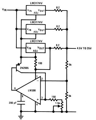
The LM317HV adjustable regulator is capable of supplying over 1.5A across an output voltage range of 1.2V to 57V. The design of this high current power supply is straightforward, as the LM317HV requires only a few external resistors to...
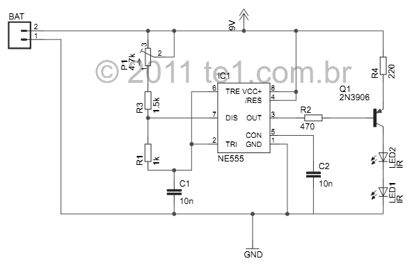
This small device is designed to jam remote controls by directing it at the TV. The circuit utilizes a 555 timer configured as an astable multivibrator, generating a frequency of approximately 38 kHz, which corresponds to the frequency at...
This simple variable power supply circuit has a low production cost and delivers an output voltage between 1.5 V and 15 V with a maximum current of 500 mA. This variable power supply circuit is designed to provide a versatile...
A variable audio oscillator operates within a frequency range of 20 hertz to 20 kilohertz. The circuit utilizes an Intersil 8038 waveform generator, which is designed in a 14-pin dual in-line package (DIP). The variable audio oscillator circuit is designed...