
Interfacing Relay To Microcontroller

The relay driver circuit serves as an interface between low-power control signals and high-power loads. In this specific configuration, the circuit utilizes an NPN transistor, specifically the BC547, to switch the relay. The relay operates on a specified voltage, typically 5V or 12V, and requires a certain amount of current to activate its coil, which is generally between 25mA to 70mA.
The operation begins when a logic high signal (LOGIC 1) is applied to the base of the BC547 transistor. This signal allows current to flow from the collector to the emitter, effectively driving the transistor into saturation. In this state, the transistor acts as a closed switch, allowing a larger current to flow through the relay coil. This current energizes the relay, causing it to switch its contacts and control the connected load.
The relay itself consists of an electromagnetic coil and a set of contacts. When the coil is energized, it generates a magnetic field that attracts a movable armature, causing the contacts to either open or close, depending on the relay's design. This action can control various devices, such as motors, lights, or other high-voltage appliances, without exposing the low-power control circuit to high voltages or currents.
It is essential to ensure that the transistor is appropriately biased to operate within its safe limits, preventing damage during operation. Additionally, a flyback diode is often connected in parallel with the relay coil to protect the transistor from voltage spikes generated when the relay is de-energized. This diode allows the inductive kickback generated by the collapsing magnetic field of the relay coil to dissipate safely, thus prolonging the lifespan of the transistor and ensuring reliable operation of the circuit.Relays are devices which allow low power circuits to switch a relatively high Current/Voltage ON/OFF. For a relay to operate a suitable pull-in & holding current should be passed through its coil. Generally relay coils are designed to operate from a particular voltage often its 5V or 12V. The function of relay driver circuit is to provide the necessary current (typically 25 to 70ma) to energize the relay coil.
Figure 1 shows the basic relay driver circuit. As you can see an NPN transistor BC547 is being used to control the relay. The transistor is driven into saturation (turned ON) when a LOGIC 1 is written on the PORT PIN thus turning ON the relay. The relay 🔗 External reference
Related Circuits
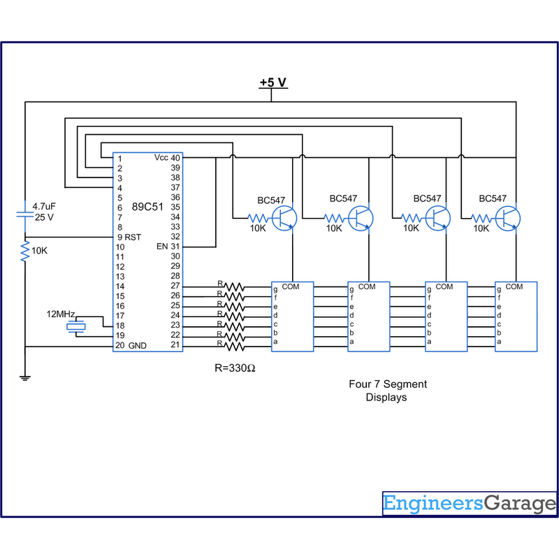
A digital clock displays time in a digital format. The circuit outlined here shows the time with double-digit minutes and two digits for seconds across four seven-segment displays. The segments of the displays are interconnected with the 8051 microcontroller...
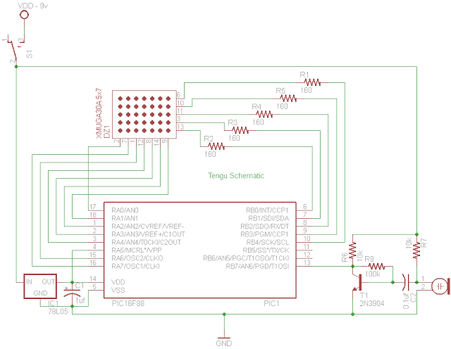
Tengu derives its name from a mythical Japanese creature known for getting into mischief. However, this Tengu is more earthly in nature. It responds to voice and sounds, changing its facial features depending on the intensity of the sound....
RFID technology is highly versatile, has numerous applications, and has become affordable and easy to implement in recent times. This tutorial outlines the process of interfacing an RFID Reader with a standard Atmel AVR microcontroller. RFID (Radio Frequency Identification) systems...
Extended periods of bright sunshine and warm weather can cause even large storage batteries in solar power systems to become quite warm. Therefore, a circuit is typically connected in parallel with the storage battery to either engage a high-power...

This article continues from the previous one regarding the single character LCD display using an AVR microcontroller. The prior article demonstrated how to display a single letter on an LCD. This article advances the learning process by explaining how...
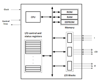
Microcontrollers are integrated circuits that consist of a microprocessor along with additional units such as memory and input/output peripherals. This implementation allows for savings in time, space, and cost. Microcontrollers are commonly abbreviated as MCU (Microcontroller Unit), µC, or...