
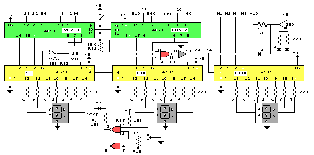
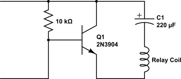
Solar Relay

The circuit described is designed to manage the thermal conditions of storage batteries in solar power systems effectively. It integrates a relay-based control mechanism that mitigates the risk of overheating by utilizing a solar light probe to monitor environmental conditions. The relay's coil resistance specification ensures compatibility with the system's operational parameters, allowing for reliable engagement and disengagement based on solar intensity. The use of parallel-connected photo-transistors enhances sensitivity to light, ensuring that the relay activates promptly in response to increased solar radiation. The NTC thermistor plays a critical role in temperature compensation and operational stability, providing a feedback mechanism that helps maintain the desired relay state under varying thermal conditions. Overall, this circuit exemplifies a practical solution for optimizing battery management in solar applications, particularly during peak sunlight hours.With extended periods of bright sunshine and warm weather, even relatively large storage batteries in solar-power systems can become rather warm. Consequently, a circuit is usually connected in parallel with the storage battery to either connect a high-power shunt (in order to dissipate the excess solar power in the form of heat) or switch on a ve
ntilation fan via a power FET, whenever the voltage rises above approximately 14. 4 V. However, the latter option tends to oscillate, since switching on a powerful 12-V fan motor causes the voltage to drop below 14. 4 V, causing the fan to be switched off. In the absence of an external load, the battery voltage recovers quickly, the terminal voltage rises above 14.
4 V again and the switching process starts once again, despite the built-in hysteresis. A solution to this problem is provided by the circuit shown here, which switches on the fan in response to the sweltering heat produced by the solar irradiation instead of an excessively high voltage at the battery terminals. Based on experience, the risk of battery overheating is only present in the summer between 2 and 6 pm.
The intensity of the sunlight falling within the viewing angle of a suitably congured sun probe` is especially high precisely during this interval. This is the operating principle of the solar relay. The trick to this apparently rather simple circuit consists of using a suitable combination of components.
Instead of a power FET, it employs a special 12-V relay that can handle a large load in spite of its small size. This relay must have a coil resistance of at least 600 , rather than the usual value of 100-200 . This requirement can be met by several Schrack Components relays (available from, among others, Conrad Electronics).
Here we have used the least expensive model, a type RYII 8-A printed circuit board relay. The light probe is connected in series with the relay. It consists of two BPW40 photo-transistors wired in parallel. The type number refers to the 40-degree acceptance angle for incident light. In bright sunlight, the combined current generated by the two photo-transistors is sufficient to cause the relay to engage, in this case without twitching. Every relay has a large hysteresis, so the fan connected via the a/b contacts will run for many minutes, or even until the probe no longer receives sufficient light.
The NTC thermistor connected in series performs two functions. First, it compensates for changes in the resistance of the copper wire in the coil, which increases by approximately 4 percent for every 10 C increase in temperature, and second, it causes the relay to drop out earlier than it otherwise would (the relay only drops out at a coil voltage of 4 V). Depending on the intended use, the 220- resistance of the thermistor can be modified by connecting a 100- resistor in series or a 470- resistor in parallel.
If the photo-transistors are fastened with the axes of their incident-angle cones in parallel, the 40-degree incident angle corresponds to 2 pm with suitable solar orientation. If they are bent at a slight angle to each other, their incident angles overlap to cover a wider angle, such as 70 degrees.
With the tested prototype circuit, the axes were oriented nearly parallel, and this fully met our demands. The automatic switch-off occurs quite abruptly, just like the switch-on, with no contact jitter. This behavior is also promoted by the NTC thermistor, since its temperature coefficient is opposite to that of the PTC` relay coil and approximately five times as large.
This yields exactly the desired effect for energizing and de-energizing the relay: a large relay current for engagement and a small relay current for disengagement. Building the circuit is actually straightforward, but you must pay attention to one thing. The photo-transistors resemble colorless LEDs, so there is a tendency to think that their pinning` is the same as that of LEDs, with the long lead being positive and the short lead negative.
However, with the BPW40 the situation is exactly the opposite; the short lead is the collector lead. Naturally, the back-emf diode for the relay must also be connected with the right polarity. The residual current on cloudy days and at night is negligibly small. 🔗 External reference
Related Circuits
This device is a combination digital clock timer and solar panel charge controller designed to maintain a deep cycle battery charged by a solar panel. The timer output controls a 12-volt load for a 32-minute interval each day. The...
A single-coil latching relay is utilized, which can latch and reset with opposite polarities. Testing of the circuit with dual opposite-biased LEDs showed no flickering in either direction, indicating stable charge and discharge behavior. However, there are concerns regarding...
It was one of those days when learning chemistry, philosophy, and literature seemed necessary. Contemplating my plans for the day, I decided to embark on a project that I had wanted to undertake for a long time but had...
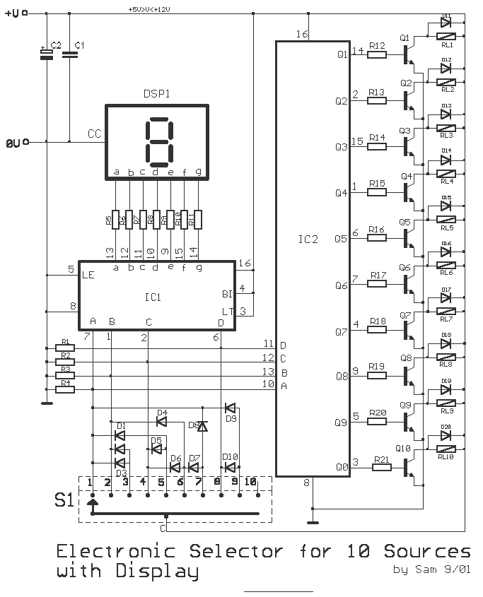
This is a circuit for alternative sources selection. It combines mechanical selection using a rotating switch S1, the electronic drive of the relays RL 1-10 and also the optical indication of the selection by the Display DSP1. The function...
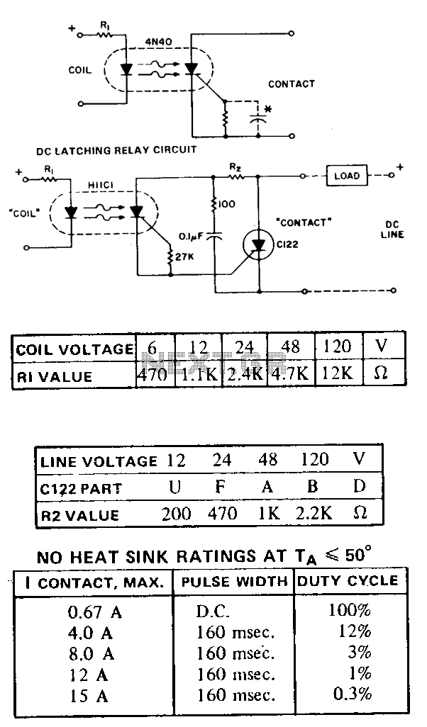
The HllC provides a de-latching relay function and reverse polarity blocking for currents up to 300 mA, depending on the ambient temperature. For direct current (DC) applications, a gate cathode resistor may be supplemented with a capacitor to reduce...
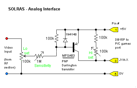
The analog interface is a straightforward analog-to-digital converter that accepts the analog video output from the RF/IF board and converts it into a format that can be read by a PC games port. The joystick input of the games...