
inverter circuit
This inverter circuit operates by utilizing a basic transformer-based design to convert low-voltage DC into high-voltage AC. The core components include two power transistors (Q1 and Q2), which act as switches, rapidly alternating the current flow through the transformer (T1). This switching action generates an alternating magnetic field in the transformer, inducing an AC voltage in the secondary winding.
The choice of transistors is crucial, as they must be capable of handling the expected current load. The 2N3055 transistors are a common choice for moderate power applications, but for higher wattage needs, transistors with higher current ratings should be selected. The transformer (T1) is also a significant factor in determining the output wattage; a transformer with an appropriate rating will ensure efficient operation without overheating.
When rewinding a microwave transformer, the primary winding remains intact, while the high-voltage secondary is replaced with a new winding designed for lower voltages. The winding process should be performed with precision to maintain the transformer's efficiency. The center tap created during winding allows for the effective use of both halves of the AC cycle, improving overall performance.
Capacitance in the circuit is provided by tantalum capacitors, which are necessary for smoothing the output and preventing voltage spikes that could damage the transistors. The specific capacitance value of 68uF is critical for proper operation, and any substitutions could lead to circuit instability.
For users interested in generating higher AC voltages, the design can be modified by selecting a transformer with a higher primary voltage rating. It is important to consider the increased current demands when operating at higher voltages, as this will affect the design and component selection.
Overall, this inverter circuit is a versatile solution for converting DC to AC power for use in various applications, particularly in off-grid scenarios such as camping or mobile setups. Proper attention to component selection, winding techniques, and circuit assembly will ensure reliable operation and longevity of the inverter.Have you ever wanted to run a TV, stereo or other appliance while on the road or camping Well, this inverter should solve that problem. It takes 12 VDC and steps it up to 120 VAC. The wattage depends on which tansistors you use for Q1 and Q2, as well as how "big" a transformer you use for T1.
The inverter can be constructed to supply anywhere fro m 1 to 1000 (1 KW) watts. Important: If you have any questions or problems with the circuit, see the forum topic linked to in the Notes section. It will answer all your questions and provide links to many other (and better) inverter circuits. Q1 and Q2, as well as T1, determine how much wattage the inverter can supply. With Q1, Q2=2N3055 and T1= 15 A, the inverter can supply about 300 watts. Larger transformers and more powerful transistors can be substituted for T1, Q1 and Q2 for more power.
The easiest and least expensive way to get a large T1 is to re-wind an old microwave transformer. These transformers are rated at about 1KW and are perfect. Go to a local TV repair shop and dig through the dumpster until you get the largest microwave you can find. The bigger the microwave the bigger transformer. Remove the transformer, being careful not to touch the large high voltage capacitor that might still be charged.
If you want, you can test the transformer, but they are usually still good. Now, remove the old 2000 V secondary, being careful not to damage the primary. Leave the primary in tact. Now, wind on 12 turns of wire, twist a loop (center tap), and wind on 12 more turns. The guage of the wire will depend on how much current you plan to have the transformer supply. Enamel covered magnet wire works great for this. Now secure the windings with tape. Thats all there is to it. Remember to use high current transistors for Q1 and Q2. The 2N3055`s in the parts list can only handle 15 amps each. You must use tantalum capacitors for C1 and C2. Regular electrolytics will overheat and explode. And yes, 68uF is the correct value. There are no substitutions. This circuit can be tricky to get going. Differences in transformers, transistors, parts substitutions or anything else not on this page may cause it to not function. If you want to make 220/240 VAC instead of 120 VAC, you need a transformer with a 220/240 primary (used as the secondary in this circuit as the transformer is backwards) instead of the 120V unit specified here.
The rest of the circuit stays the same. But it takes twice the current at 12V to produce 240V as it does 120V. Check out this forum topic to answer many of the most commonly asked questions about this circuit: 12 - 120V Inverter Again. It covers the most common problems encountered and has some helpful suggestions. 🔗 External reference
Related Circuits
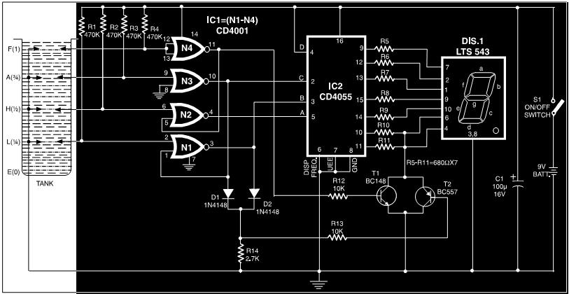
This circuit is a fluid level indicator that displays each level using meaningful English letters. It employs a seven-segment display to represent the letters E for empty, L for low, H for half, A for above average, and F...
The output current of the control circuit must be amplified when the gate current needed to trigger the device exceeds the output current of the control circuit. To achieve the amplification of the control circuit output current, a suitable transistor...
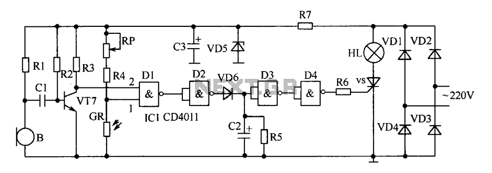
The delay-saving lamp circuit functions as a sound and light control delay energy-saving lighting system. It can directly replace a standard light switch without modifying the existing lighting circuits. In bright or daytime conditions, the sound control feature ensures...
In night photography, long exposures are common, sometimes lasting several seconds to several minutes. HDR techniques often require taking a series of nine or more photos. Holding a remote trigger for an extended period can be tedious, leading to...
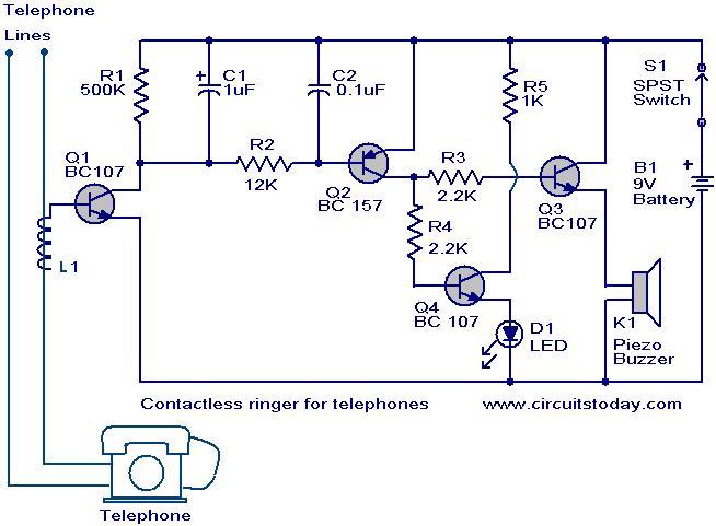
The contactless telephone ringer circuit is designed to produce an audible ring and a visual indication when a call is received. Its primary advantage lies in the absence of direct contact between the telephone line and the circuit, which...
The figures (a) and (b) illustrate AC measuring circuits. Figure 21(a) presents a current measuring schematic diagram utilizing a magnetic balanced mode Hall device. When the magnetic field generated by the measured current, denoted as IN, is B1, this...
Warning: include(partials/cookie-banner.php): Failed to open stream: Permission denied in /var/www/html/nextgr/view-circuit.php on line 713
Warning: include(): Failed opening 'partials/cookie-banner.php' for inclusion (include_path='.:/usr/share/php') in /var/www/html/nextgr/view-circuit.php on line 713