
Contactless telephone ringer circuit
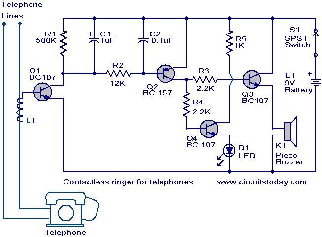
The contactless telephone ringer circuit operates by utilizing the principles of electromagnetic induction to detect the ringing signal from a telephone line without direct electrical contact. The circuit consists of several key components: a coil (L1), a series of transistors (Q1, Q2, Q3, Q4), a buzzer, an LED, and a switch (S1).
When a call comes in, the telephone line generates a 60 Hz AC ringing signal, which creates a fluctuating magnetic field around the wires. Coil L1, placed near the telephone line, captures this magnetic field. The design of L1, with its 50 turns of 28 SWG enameled copper wire, is crucial for maximizing the induced voltage through electromagnetic induction. The voltage induced in L1 is sufficient to bias transistor Q1 into conduction.
Once Q1 is activated, it allows current to flow through subsequent transistors Q2, Q3, and Q4, effectively creating a pathway for current to energize both the buzzer and the LED. The buzzer provides an audible alert, while the LED offers a visual cue, indicating that a call is incoming. The inclusion of switch S1 allows users to easily turn the circuit on or off, providing flexibility in its operation.
It is essential to ensure that the coil is properly installed and that the connections are secure to avoid any malfunctions. Users should also be aware of local regulations regarding the use of such devices with telephone lines, as unauthorized use may result in legal repercussions. Proper research and compliance with legal requirements are recommended before proceeding with the construction and use of this circuit.The contact less telephone ringer circuit can produce a ring as well as a visual indication when a call comes. The main advantage is that since there is no direct contact between the phone line and the circuit there is no chance for a loading or disturbance in the telephone line.
When the telephone rings 60 Hz AC signal is generated which produces a proportional magnetic field around the telephone lines. These magnetic field will be picked up by the coil L1 due to electromagnetic induction. A proportional voltage is developed across L1 and it will bias transistor Q1 to ON. This results in the conduction of transistors Q2, Q3 andQ4. The buzzer will ring and the LED will glow. The switch S1 acts as an ON/OFF switch. For L1 make 50 close turns of 28 SWG enameled copper wire on any of the two telephone wires. Connect one end of the coil to base of Q1 and leave other end free. Use of this type or any other devices other than the allowed telephones and devices with the telephone line may be a law violation in some nations. Check it properly before trying. 🔗 External reference
Related Circuits
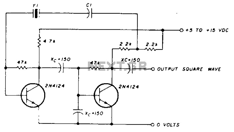
A transistor in series with capacitor C1 can be utilized to adjust the oscillator output frequency. The frequency may vary with changes in capacitance ranging from 20 pF to 0.01 µF, or as determined by the tuning capacitor. The...
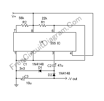
If a negative supply is required for an operational amplifier or if a negative bias voltage is needed while operating from a single supply voltage, such as in battery applications. To generate a negative supply voltage from a single positive...
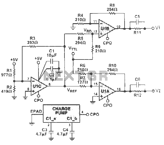
The circuit can incorporate a buffer gate at the input to ensure compatibility with TTL or other logic levels. This design is intended for a TTL 0V circuit to accommodate a 3.5V input signal swing. Additionally, it generates a...
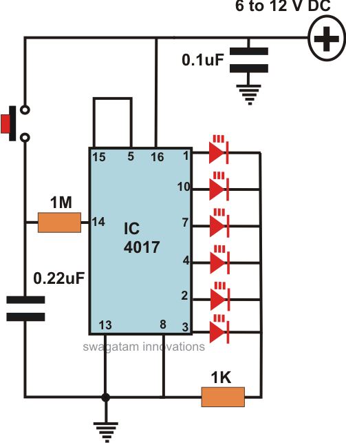
This article offers a circuit diagram and a discussion on CMOS logic and IC layout for creating a set of attention-getting LED running lights. It details a simple sequential LED flasher or light chaser that can be built, including...
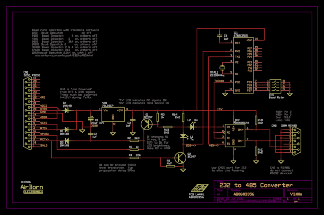
The new version of the RS485 interface addresses the issues associated with RTS control, which was a challenge in the previous design. However, implementing this solution requires a microprocessor, adding complexity to the design. This unit is currently being...
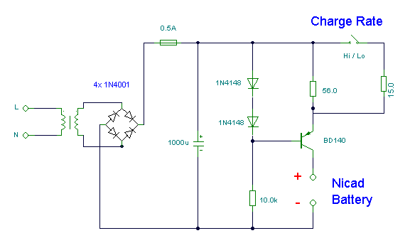
This simple charger utilizes a single transistor as a constant current source. The voltage across the pair of 1N4148 diodes biases the base of the BD140 medium power transistor. The circuit operates by employing the BD140 transistor to regulate the charging...
Warning: include(partials/cookie-banner.php): Failed to open stream: Permission denied in /var/www/html/nextgr/view-circuit.php on line 713
Warning: include(): Failed opening 'partials/cookie-banner.php' for inclusion (include_path='.:/usr/share/php') in /var/www/html/nextgr/view-circuit.php on line 713