
circuit trigger camera phone pda mp3
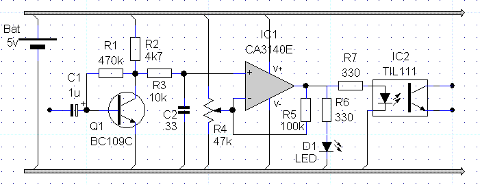
The circuit described is a DIY camera remote trigger designed for long exposure photography, particularly in low-light conditions. It utilizes a mobile device's audio output to control the camera's shutter release, allowing photographers to automate the process of taking multiple exposures without manually pressing the shutter button. The circuit operates by detecting audio signals from the mobile device, which are then processed to simulate a button press on the camera's remote trigger input.
Key components of the circuit include a decoupling capacitor (C1) to stabilize the power supply, a transistor (Q1) for signal amplification, and a filtering capacitor (C2) to clean the signal before it is fed into the comparator (IC1). The comparator is crucial for determining when the audio signal is present and adjusting the circuit's sensitivity via resistor R4. An LED indicator (D1) provides visual feedback, signaling when the shutter is actively being released.
The opto-isolator (IC2) is a critical component that ensures electrical isolation between the mobile device and the camera, preventing any potential damage to either device due to voltage spikes or incorrect connections. The circuit is designed to be powered by a 5V supply, with plans for adaptation to a 9V battery to improve longevity during extended shooting sessions. The use of commonly available components makes this project accessible for hobbyists and enthusiasts looking to enhance their photography capabilities without incurring high costs.
Future iterations of the design will likely include enhancements based on user feedback and practical testing, including modifications to improve reliability and expand compatibility with various camera models. The accompanying software will provide a user-friendly interface for programming exposure sequences, making it easier for photographers to experiment with different settings and achieve desired results in their long exposure photography endeavors.On night photography, long exposures are the norm: sometimes several seconds, and sometimes several minutes; I also tend to employ HDR techniques, and that means that I often end making series of nine or even more photos all together. Spending half an hour (sometimes more) with the remote trigger on your hand can be quite boring, so I toyed with the idea of making this process
authomatic. and I found a way to control the camera from a mobile phone, a PDA, or even an MP3 player. One of my favorite `recipes` stats with a one-second exposure, and then I double the time on each take, up to a final four-minute exposure; but, when the scene is specially dark, it may require more exposures, up to thirty seconds. My problem is that cameras are generally not ready for this type of work: it is uncommon to find cameras capable of doing exposures longer than 30 seconds, and automated sequences of nine exposures are quite rare too.
There are commercially available intervalometers, sure; but they are expensive, and I have never heard of one capable of doing this type of series. So I began wandering on the idea of building one myself, as cheap as possible. My camera (a Canon 400D) has a specific connector for remote triggers, which can be used to release the shutter quite easily; in fact, there is a myriad of schemes on Internet to build your own trigger.
And I came to the conclusion that the easiest way to make one would be to connect the camera to a mobile phone: this way I could control the timing by software, and have an almost infinite flexibility; all I needed was to make that connection possible. And I figured I could use the earphone output from the mobile telephone: using the circuit shown here, it is possible to connect the audio output from the gadget to the remote trigger input from the camera.
Basically, we just need to detect when there is a sound on the output, and simulate a press on the trigger release button while that sound lasts. Then, using a small JavaME application we could produce beeps of controlled length, and those beeps would control the shutter on the camera.
WARNING: I must warn readers that I am not a professional of electronics; I cannot guarantee that this circuit will not fail, or that it will not break your camera, I cannot event guarantee that it will not produce alopecia: it works for me, and I tried to make it completely safe both for the camera and the mobile phone. But I cannot take any responsibility. The output form the sound source enters through the connector at the left. C1 is just a decoupling capacitor. Then, the signal is amplified at Q1 and filtered by C2. IC1 is used as a comparator, and R4 is there to adjust the circuit to the signal level at the input (usually, it can be left at the intermediate position).
D1 is an activity indicator LED, which should go off when the circuit releases the shutter. Finally, IC2 is an opto-isolator, and at the other side we have the connectors that go to the camera; in my case, I used a 2. 5mm stereo JACK. As can be seen, the circuit can be used with a 5v power source, because that is what I had available at the moment; but my intention is to adapt it to use a 9v battery: I do not expect having to change more that a couple of resistors.
In fact, I think that none of the components has a critical value, I made this with what I had lying around. Soon I will publish the modified version, along with photos of the real construction of the device; I will also publish the software used to drive the camera.
Considering that the input to this circuit is the earphone output from the mobile phone, it could be used with almost any PDA, instead of the mobile phone. In fact, it could also be used with an MP3 player, if we previously record a sequence of beeps on a computer, and we put that `song` into the player; then, reproducing that song with the player connected to the camera through this circuit, we would
🔗 External reference
Related Circuits
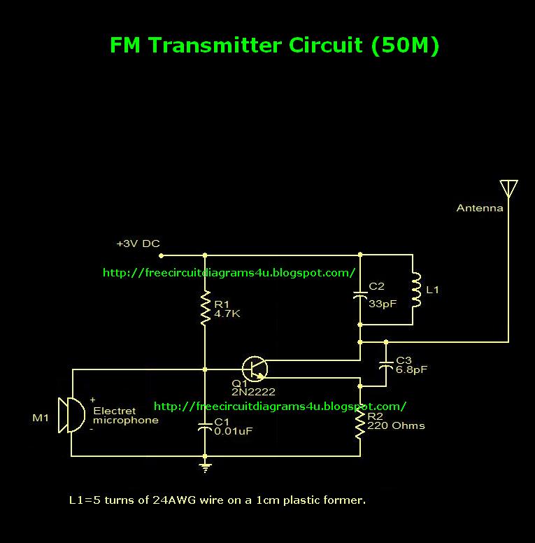
This is an FM transmitter circuit diagram. This circuit uses a 2N2222 transistor, allowing it to operate at 3V and transmit signals up to 50 meters. The FM transmitter circuit consists of several key components, primarily centered around the 2N2222...
The circuit switches the current to an electrical heater on and off to maintain the temperature of a room at 25 ±0.5°C. The temperature sensor is a thermistor that provides a differential input (for reduced noise) to an operational...
As dusk begins to fall, the sensor, which is a cadmium-sulfide light-dependent resistor (LDR), activates a small horn to provide an audible reminder to turn on the lights. The circuit can be turned off by simply switching on the...
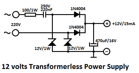
One of the major problems that must be addressed in electronic circuit design is the generation of low voltage DC power supply from mains power to energize the circuit. In electronic circuit design, the conversion of mains AC voltage to...
This electronic schematic allows for the design of a simple cellular phone detector circuit capable of sensing the presence of an activated mobile phone from a distance of 1.5 meters. The capacitor C3 should have lead lengths of 18...
High-voltage power supply circuit for fluorescent light power supply. Refer to that page for an explanation of the related circuit diagram. The high-voltage power supply circuit designed for fluorescent lights typically consists of several key components that work together to...
Warning: include(partials/cookie-banner.php): Failed to open stream: Permission denied in /var/www/html/nextgr/view-circuit.php on line 713
Warning: include(): Failed opening 'partials/cookie-banner.php' for inclusion (include_path='.:/usr/share/php') in /var/www/html/nextgr/view-circuit.php on line 713