
Inverter Circuit For Soldering Iron
The inverter circuit operates by converting DC voltage from a battery source into an AC voltage suitable for the operation of small soldering irons. The design typically consists of an oscillator stage that generates a square wave signal, which is then amplified and transformed into a higher voltage AC signal.
The use of eight transistors in the circuit serves multiple purposes. Firstly, they are arranged in a push-pull configuration to drive the transformer, which steps up the voltage to the required level for the soldering iron. The oscillator circuit is usually built using two transistors that alternate their conduction states, creating a square wave output. This output is fed into the base of the push-pull transistors, driving them into saturation and allowing current to flow through the primary winding of the transformer.
The transformer plays a critical role in this inverter design. It not only steps up the voltage but also provides isolation between the DC source and the AC output, enhancing safety during operation. The secondary winding of the transformer is connected to the soldering iron, delivering the necessary voltage and current for its operation.
Additional components may include resistors, capacitors, and diodes, which help stabilize the circuit, filter noise, and protect against voltage spikes. Proper heat dissipation mechanisms should be considered for the transistors, as they may generate significant heat during operation.
Overall, this inverter circuit is an effective solution for powering small soldering tools in environments without access to mains electricity, making it a valuable addition to portable soldering setups.Here is a simple but inexpensive inverter for using a small soldering iron (25W, 35W, etc) In the absence of mains supply. It uses eight transistors and a.. 🔗 External reference
Related Circuits
PC parallel port can be very useful I/O channel for connecting your own circuits to PC. The PC's parallel port can be used to perform some very amusing hardware interfacing experiments. The port is very easy to use when...
This is a true subwoofer circuit designed specifically for 15- to 18-inch woofers and is not compatible with 6- or 8-inch subwoofers. It features a bass-reflex design. The true subwoofer circuit operates by utilizing a bass-reflex enclosure, which enhances low-frequency...
Model Railroader is the world's largest magazine on model trains and model railroad layouts. It offers assistance for both beginners and advanced enthusiasts across all model railroading scales, including layout track plans, product reviews, news, and forums. Model Railroader magazine...

The LM1877 is a stereo amplifier designed to deliver 2W per channel into 8-ohm loads. It is intended to operate with a minimal number of external components, making it a versatile integrated circuit suitable for various audio amplification applications,...
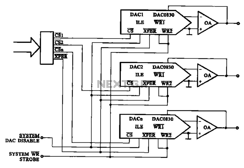
A multi-channel D/A converter circuit is presented, illustrating its fundamental structure. This circuit effectively converts encoded digital signals into multiplexed analog signal outputs. The multi-channel Digital-to-Analog (D/A) converter circuit is designed to facilitate the conversion of digital signals into corresponding...
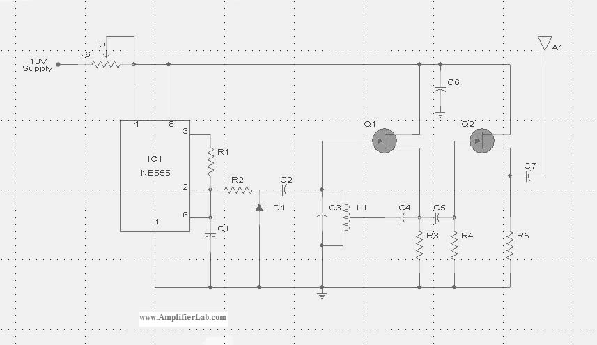
The circuit diagram of the Radio Collar Transmitter is presented here. This circuit is based on the NE555 integrated circuit, which serves as the central component. The Radio Collar Transmitter circuit utilizes the NE555 timer IC to generate a modulated...
Warning: include(partials/cookie-banner.php): Failed to open stream: Permission denied in /var/www/html/nextgr/view-circuit.php on line 713
Warning: include(): Failed opening 'partials/cookie-banner.php' for inclusion (include_path='.:/usr/share/php') in /var/www/html/nextgr/view-circuit.php on line 713