
Radio Collar Transmitter Circuit
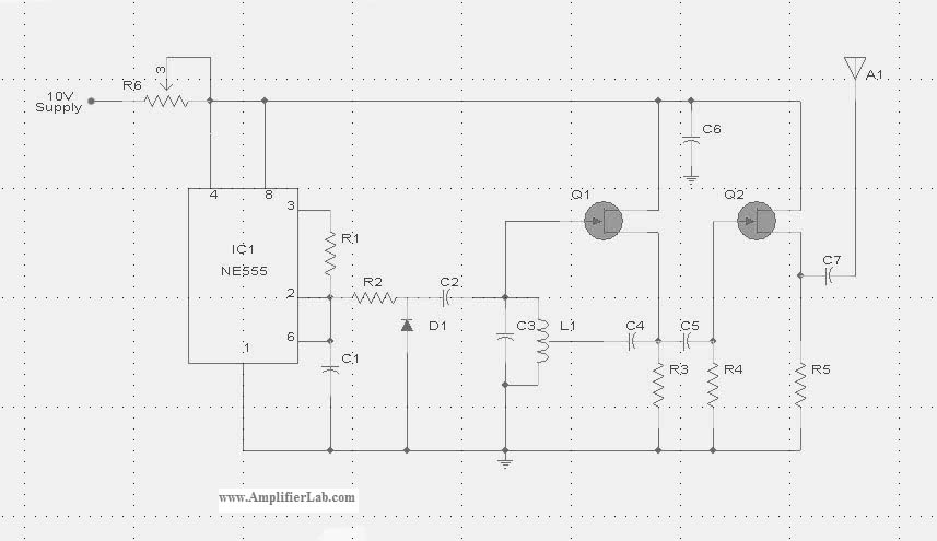
The Radio Collar Transmitter circuit utilizes the NE555 timer IC to generate a modulated signal suitable for transmission. The NE555 can be configured in astable mode to produce a continuous square wave output, which is essential for creating the radio frequency signal. This signal can then be amplified and transmitted via an antenna.
In the typical configuration, the NE555 is connected with resistors and capacitors that determine the frequency and duty cycle of the output waveform. The frequency is set by the values of the resistors (R1 and R2) and the capacitor (C1) connected to the timing pins of the NE555. The duty cycle can be adjusted by varying R1 and R2, allowing for flexibility in the modulation of the output signal.
The output from the NE555 is then fed into a radio frequency amplifier circuit, which may consist of a transistor or a dedicated RF amplifier IC. This stage boosts the signal strength to ensure that it can be effectively transmitted over a distance. The amplified signal is then connected to an antenna, which converts the electrical signals into radio waves.
Power supply considerations are also critical in the design of the Radio Collar Transmitter. Typically, a battery or a small power source is used to provide the necessary voltage and current for the circuit. Proper decoupling capacitors should be included to filter out noise and ensure stable operation of the NE555 timer.
Overall, the Radio Collar Transmitter circuit is a practical application of the NE555 timer IC, showcasing its versatility in generating modulated signals for wireless communication purposes. Proper layout and component selection are essential for optimizing the performance and range of the transmitter.The circuit diagram of Radio Collar Transmitter has been described here. This circuit is based on the IC NE 555 which is the central part. 🔗 External reference
Related Circuits

In this circuit, an additional exclusive-OR gate is connected after the modulo-2 feedback, with CI and R2 applying the supply turn-on ramp into the feedback loop. This provides sufficient transient signal so that the PRBS generator can self-start during...
Here are the schematics for infrared remotes. This remote transmits a tone using an infrared LED. This tone is decoded by the receiver. Since the receiver only switches when it "hears" the tone, there are no accidental activations. The schematic...
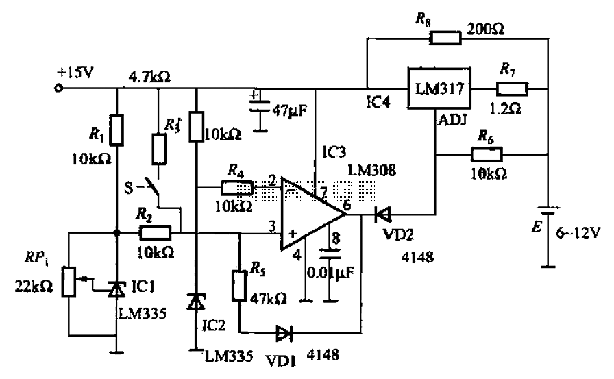
When fast charging a nickel-cadmium battery, the temperature control circuit, as illustrated in the accompanying figure, is designed to monitor the battery temperature to regulate the charging current. The circuit consists of Icl to IC3, which forms the temperature...
This circuit gives a low-level output when sufficient lighting is present, functioning as a light detector. It can issue a command to turn on lights when darkness falls. Its output is compatible with TTL levels, providing a low logic...
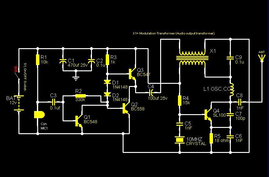
The core component of this circuit is a crystal oscillator utilizing a 10MHz crystal to generate a highly stable carrier frequency. The sound signal from a condenser microphone is amplified by an amplifier circuit comprised of transistors Q1, Q2,...
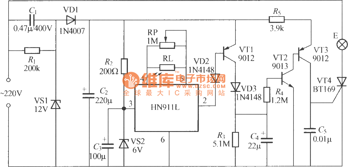
The figure illustrates an automatic light sensing system utilizing the HN911L pyroelectric infrared detection module. The HN911L incorporates high-sensitivity infrared sensors, a passive infrared (PIR) sensor, amplifiers, a signal processing circuit, and an output circuit. This module is capable...
Warning: include(partials/cookie-banner.php): Failed to open stream: Permission denied in /var/www/html/nextgr/view-circuit.php on line 713
Warning: include(): Failed opening 'partials/cookie-banner.php' for inclusion (include_path='.:/usr/share/php') in /var/www/html/nextgr/view-circuit.php on line 713