
Inverter Circuit For Soldering Iron circuit
The inverter circuit operates by converting a DC voltage into an AC output suitable for powering low-wattage devices such as soldering irons. The astable multivibrator configuration formed by Q1 and Q2 is crucial as it establishes the frequency of the output signal. The frequency of 50Hz is standard for many applications, particularly in regions where the mains supply frequency is aligned with this value.
The output from the astable multivibrator is a square wave, which is then amplified by the Darlington pairs Q3-Q5 and Q4-Q6. The Darlington configuration is advantageous due to its high current gain, allowing the circuit to drive higher loads without requiring excessive base current. This characteristic is particularly important for applications that demand higher power outputs from low-power input signals.
In this design, Q3 and Q4 serve as the driver transistors, while Q5 and Q6 provide additional amplification. The use of BC558 and BD140 transistors in the Darlington pair configuration ensures that the output stage can handle the necessary current to power the soldering iron effectively. The circuit is completed with passive components such as resistors and capacitors, which stabilize the operation and filter the output signal.
Overall, this inverter circuit is an efficient solution for providing AC power in situations where conventional mains electricity is unavailable, making it a practical tool for hobbyists and professionals needing a portable soldering solution. Proper attention to component ratings and thermal management is advisable to ensure reliable operation, especially when driving devices with varying power demands.Here is a simple but inexpensive inverter for using a small soldering iron (25W, 35W, etc) In the absence of mains supply. It uses eight transistors and a few resistors and capacitors. Transistors Q1 and Q2 (each BC547) form an astable multivibrator that produces 50Hz signal. The complementary outputs from the collectors of transistors Q1 and Q2 are fed to pnp Darlington driver stages formed by transistor pairs Q3-Q5 and Q4-Q6 (utilising BC558 and BD140)..
🔗 External reference
Related Circuits
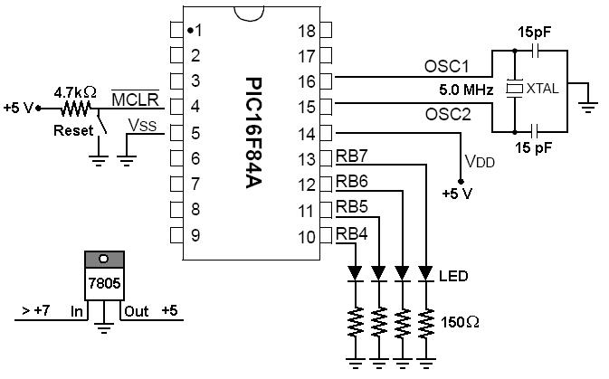
To start working with microcontrollers, several essential items are required. The PICSTART Plus kit, part number DV003001, was purchased from Microchip. This kit contains a sample PIC16F84 microcontroller chip, which in this case is a PIC16F84A chip. This chip...
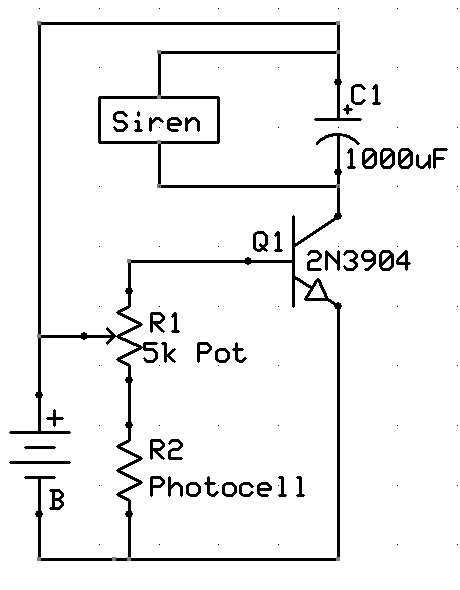
A new user has recently discovered a Laser Alarm System and has decided to explore this project. The Laser Alarm System is a security device that utilizes laser beams to detect unauthorized entry or movement within a designated area. The...
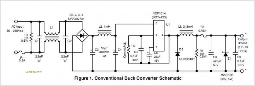
Quasi square wave resonant converters, also referred to as quasi resonant (QR) converters, facilitate the design of flyback Switch Mode Power Supplies (SMPS) with diminished Electro Magnetic Interference (EMI) and enhanced efficiency. Due to their low noise generation, QR...
A NE555 integrated circuit (IC) is utilized for the design of a variable low-frequency oscillator, and a schematic is provided. The NE555 timer IC is a versatile and widely used device in various electronic applications, particularly in generating precise timing...
Field strength meters are essential tools for individuals working with radio transmitter electronics. The following is an example of a circuit that serves this purpose. A field strength meter circuit typically consists of several key components, including an antenna, a RF...
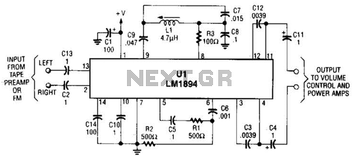
UL is a dedicated integrated circuit (IC) from National Semiconductor that achieves up to 10 dB noise reduction through an adaptive bandwidth scheme and a psychoacoustic masking technique. The UL integrated circuit is designed to enhance audio performance by significantly...