
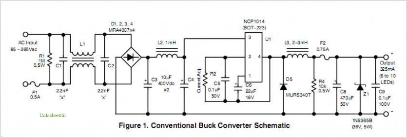
700 Ma Led Power Supply circuit using Monolithic Controller
Quasi resonance typically pertains to the integration of a conventional hard-switching converter with a resonant tank. While the control operation mirrors that of a standard PWM controller, an additional network is incorporated to shape variables around the MOSFET, either current or voltage. Depending on the operational mode, it is possible to switch at zero current (ZCS) or zero voltage (ZVS). In comparison to a traditional PWM converter, QR operation results in lower switching losses; however, the RMS current flowing through the MOSFET increases, leading to higher conduction losses. With meticulous design, efficiency can be optimized. A primary advantage of quasi resonance is the reduced spectral content, whether conducted or radiated. True ZVS quasi resonance results in a voltage waveform on the switch that resembles a sinusoidal arc.
Quasi square wave resonant converters are pivotal in modern power supply design, particularly in applications where electromagnetic compatibility is critical. The ability to operate with reduced EMI makes them an excellent choice for consumer electronics, where interference with RF signals can degrade performance. The NCP1207 controller exemplifies the practical implementation of QR technology, providing designers with a robust solution that balances efficiency and noise reduction.
In terms of circuit design, the integration of a resonant tank with a hard-switching converter necessitates careful consideration of component selection and layout. The resonant tank typically consists of inductors and capacitors that are tuned to resonate at the desired switching frequency. This tuning is crucial to achieving ZCS or ZVS, which significantly minimizes switching losses. The design must also account for the increased RMS current, which can affect thermal performance and efficiency.
In practical applications, the layout should minimize parasitic inductance and capacitance to maintain the integrity of the resonant operation. Additionally, the choice of MOSFETs with appropriate ratings and characteristics is essential to ensure reliable operation under the quasi resonant conditions. Implementing snubber circuits may also be beneficial to further mitigate voltage spikes and enhance overall circuit robustness.
Overall, quasi square wave resonant converters represent an advanced approach to power supply design that meets the stringent demands of modern electronics while providing significant advantages in terms of efficiency and EMI performance.Quasi ’square wave resonant converters, also known as quasi ’resonant (QR) converters, allow designing flyback Switch ’Mode Power Supplies (SMPS) with reduced Electro ’Magnetic Interference (EMI) signature and improved efficiency. Due to the low level of generated noise, QR SMPS are therefore very well suited to applications dealing with RF si
gnals, such as TVs ON Semiconductor NCP1207 is a QR controller that will ease your design of an EMI ’friendly TV power supply with only a few additional components, and able to lower its standby power down to 1. 0 W. What is Quasi ’Resonance, The term quasi ’resonance is normally related to the association of a real hard ’switching converter and a resonant tank.
While the operation in terms of control is similar to that of a standard PWM Controller an additional network is added to shape the variables around the MOSFET: current or voltage. Depending on the operating mode, it becomes possible to either Switch at zero current (ZCS) or zero voltage (ZVS).
Compared to a conventional PWM converter, a QR operation offers less switching losses but the RMS current circulating through the MOSFET increases and forces higher conduction losses; with a careful design, efficiency CAN be improved. However, one of the main advantages in favor of the quasi ’resonance is the reduced spectrum content either conducted or radiated.
True ZVS quasi ’resonance means that the voltage present on the Switch looks like a sinusoidal arch. Figure 1 shows how such a signal could look like. 🔗 External reference
Related Circuits
This circuit is used to slowly illuminate and fade a pair of red LEDs (light emitting diodes). The fading LEDs could be installed as 'eyes' in a small pumpkin or skull as a Halloween attraction, or mounted in a...
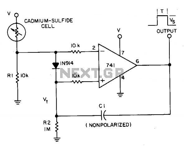
A photocell circuit provides automatic threshold adjustment. Monostable action prevents undesired retriggering of the output. With only one op amp IC, the circuit offers automatic adjustment of its trigger level to accommodate various light sources, changes in ambient light,...
Light flashing circuit. This circuit is designed to create a small lamp that flashes with a signal at a rate of one flash per second, controlled by adjusting the lamp voltage through resistor R1. The rate is adjustable to...
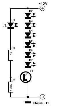
Its state is constantly changing, and this change affects the flow of current and voltage, which is visible with the two LEDs. The speed of the LED flasher can be adjusted with potentiometer P1. As an astable multivibrator, the...
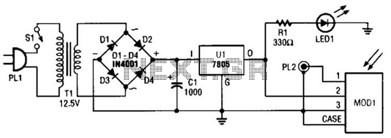
A schematic diagram for the remote analyzer is presented. The circuit is powered by a simple 5-V supply, which includes components such as PL1, SI, Tl, a bridge rectifier formed by diodes D1 through D4, capacitor CI, and a...
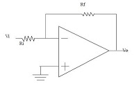
The series consists of input buffers that match the output. This configuration resembles a common collector circuit with a reinforcement factor of 1. A resistor value is included to limit the current usage. The effectiveness of this circuit largely...