
Circuit for a test circuit with the PIC16F84A

The provided assembly code snippet demonstrates a simple LED control program for the PIC16F84A microcontroller. The program initializes the microcontroller's registers and sets up the necessary configurations to control the state of LEDs connected to PORTB. The initial setup includes defining processor-specific variables and configuring the `_CONFIG` settings to disable code protection and watchdog timer features while enabling the power-up timer with the XT oscillator configuration.
The main program flow begins by loading a specific value into the working register and configuring PORTB pins for output. The program enters a loop where it calls a subroutine to change the state of the LEDs and then pauses for a brief period before repeating the process. The delay mechanism is implemented using two delay counters, and the `change_leds` subroutine manipulates the `led_counter` variable to control which LEDs are illuminated.
The program concludes with a reset routine that reinitializes the `led_counter` to a predefined value, ensuring that the LED control cycle can repeat indefinitely. This example illustrates fundamental microcontroller programming concepts, including register manipulation, subroutine calls, and delay generation, which are essential for developing embedded applications.You will need a few items to begin working with microcontrollers. I purchased the PICSTART Plus Part Number: DV003001 kit from Microchip. This kit includes the following: A sample PIC16F84 microcontroller chip: My kit actually came with a PIC16F84A chip. This is a 18 pin, 8-bit chip. The PIC16F84A data sheet is only 88 pages. So this is easier than the 18F chip. But the 16F chips do not support USB. The programmer unit: This is the device that will write the program to the chip. This will interface with a computer`s serial port. On newer computers, you may need an additional USB to Serial Converter. I am able to use this programmer for the 18 pin PIC16F and the 40 pin PIC18F chips. Compiler, Assembler and IDE. The kit comes with a copy of the MPLAB IDE. This provides a development environment for many different chips and supports C and Assembler programming languages. The IDE contains a simulator and a debugger. While you wait for the kit to be delivered, I would recommend reading the PIC16F84A data sheet. You will need to review the pin configuration on page 3. Make special note of the following: In addition to the above, you will also need some basic electronics components.
You will need an oscillator circuit. Section 6. 2 covers the oscillator configurations. The 16F84A chip has four possible oscillator configurations: LP Low Power Crystal, XT Crystal/Resonator, HS High Speed Crystal/Resonator and RC Resistor/Capacitor. A typical oscillator circuit uses a crystal and two capacitors ranging from 15 pF - 33 pF. You can get the crystal and capacitors from The Electronic Goldmine. You will need a breadboard, a IC Extraction Tool, a 5 volt regulator (7805), some LEDs and resistors.
I used low power 15mA 3volt LEDs. Doing the math, you find R=(5volt-3volt)/(15mA)=133kOhm. So, I used 150 kOhm resistors with these LEDs. You can find these at a local RadioShack. list p=16F84A #include
Related Circuits
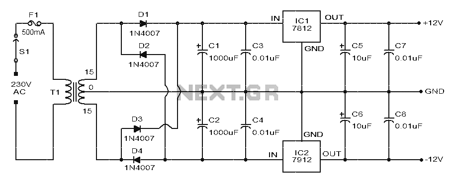
The ignition coil driver circuit described is a highly regarded design, reportedly created by Jochen Kronjaeger. It is intended to operate from a 230V source, although a modified version can function effectively at 120V. The circuit requires two ignition...

This design circuit is a tachometer circuit based on the LM2907 integrated circuit, which can provide zero-crossing data to a digital system. At each zero crossing of the input signal, the charge pump alters the state of capacitor C1...
The two circuits below illustrate the application of the 555 timer to activate a relay for a specified duration by pressing a momentary normally open (N/O) push button. The circuit on the left can be used for longer time...
This is a subwoofer low-pass filter circuit, which is another variant based on the discharge from ST Microelectronics' TL062. The TL062 is a dual high-input impedance J-FET operational amplifier characterized by low power consumption and a high slew rate....
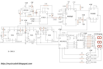
This circuit consists of a temperature sensor, amplifier, voltage-to-frequency (V/F) converter, a three-digit binary coded decimal (BCD) counter, a time base, and seven-segment LED displays. In addition to the 9400 V/F converter, other integrated circuits (ICs) required for this...

This second-order filter, designed for audio applications, utilizes an LM1458 or a similar operational amplifier. It is tunable with a cutoff frequency ranging from 30 Hz to 300 Hz. The resistors R2a and R2b are ganged log-taper potentiometers. The described...