
Invisible infrared pulsed laser
The described device functions as a pulse generator that produces adjustable frequency IR pulses, which can be utilized in various applications such as remote controls, communication systems, or sensor devices. The inverter circuit plays a crucial role in converting the low voltage from the battery pack to a high voltage necessary for generating the IR pulses.
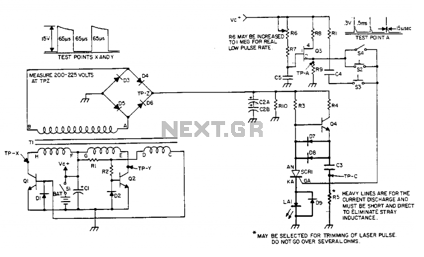
Transistor Q1 operates in a switching mode, where it alternates between conducting and non-conducting states. When Q1 is turned on, it allows current to flow through the primary winding of transformer T1, creating a magnetic field. Once Q1 saturates and turns off, the magnetic field collapses, inducing a high voltage in the secondary winding of T1. This induced voltage is then responsible for driving Q2 into saturation, facilitating the continuous generation of the pulse output.
The diodes connected to the bases of the transistors ensure that the base drive current is effectively returned, allowing the transistors to reset properly after each cycle. This feedback mechanism is vital for maintaining the stability and efficiency of the pulse generation process.
The output from the secondary of transformer T1 is a square wave voltage, which is then rectified by the integrated circuitry. Capacitor C2 serves to smooth out the rectified output, providing a stable DC voltage that can be used to power other components or systems that require a consistent voltage level for operation.
Overall, this design emphasizes the importance of careful handling due to the high voltages involved and highlights the intricate relationship between the components in achieving a reliable and adjustable IR pulse output.The device generates an adjustable frequency of low to medium powered IR pulses of invisible energy and must be treated with care. The portable battery pack is stepped up to 200 to 300 volts by the inverter circuit consisting of Ql, Q2, and Tl.
Ql conducts until saturated, at which time, the base no longer can sustain it in an "on" state and Ql turns "off," causing the magnetic field in its collector winding to collapse thus producing a voltage or proper phase in the base drive winding that turns on Q2 until saturated, repeating the above sequence of events in an "on/off" action. The diodes connected at the bases provide a return path for the base drive current. The stepped up squarewave voltage on the secondary of Tl is rectified and integrated on C2. 🔗 External reference
Related Circuits
The laser-pointer detection circuitry is capable of identifying when a laser light is directed at a specific photosensor. If the laser targets the top sensor, the comparator chip outputs a high signal. Conversely, if the laser is aimed at...
Climber A ascends a route while Climber B remains on the ground, tracking Climber A's progress with a laser pointer. The Redpointer device records the exact route taken. In Mode 1, the recorded route is played back in real-time,...
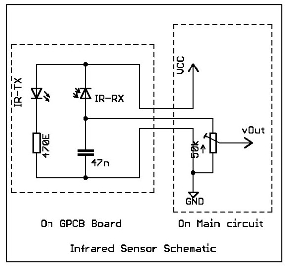
Overview: This tutorial demonstrates the creation of a simple infrared sensor module designed to detect reflecting surfaces. This sensor is capable of identifying reflective materials such as silver or white strips, as well as serving applications in obstacle detection...
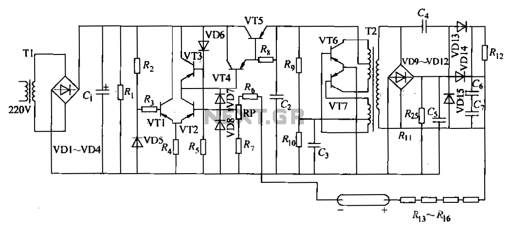
The DC power supply is a helium-neon laser excitation power supply, which is currently the most commonly used type of power supply. It is utilized in laser printers. The circuit includes a power transformer (T1), a high-voltage transformer (T2),...
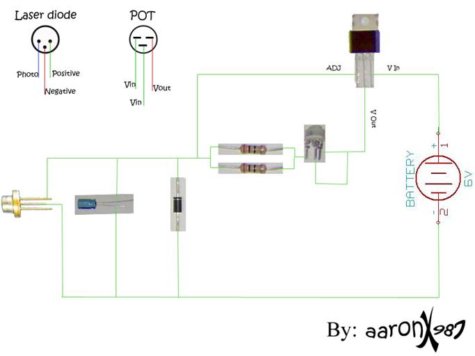
A new user expresses interest in lasers and has purchased an inexpensive red laser pointer and LED light combination keychain. The red laser pointer and LED light combination keychain is a compact and versatile device that serves multiple functions. The...
This chapter provides detailed schematics of various power supplies suitable for use with common Ar/Kr ion tubes available to hobbyists in the surplus market. Included are examples of commercial designs (Omnichrome 150R and 532 head, Lexel 88 and head)...
Warning: include(partials/cookie-banner.php): Failed to open stream: Permission denied in /var/www/html/nextgr/view-circuit.php on line 713
Warning: include(): Failed opening 'partials/cookie-banner.php' for inclusion (include_path='.:/usr/share/php') in /var/www/html/nextgr/view-circuit.php on line 713