
Laser Pointer Remote Control Circuit
The laser-pointer detection circuit employs a comparator chip to discern between two photosensors. The use of a high (5V) output when the top sensor is activated and a low (0V) output when the bottom sensor is activated allows for a straightforward logic operation. The circuit's design facilitates a memory function by incorporating a 7474 flip-flop, which retains the last state of the output, enabling it to remember whether the LED should be illuminated or not based on the most recent sensor activation.
The 7474 flip-flop, which consists of two independent 1-bit memory cells, serves as the core memory component of the circuit. This dual functionality allows for potential expansion or more complex operations in future designs. The unused cell on the chip is effectively managed by tying its inputs to a stable high voltage, ensuring that noise does not inadvertently affect circuit performance.
The output stage of the circuit is designed to drive an LED, with the inclusion of a current-limiting resistor to prevent excessive current flow that could damage the LED. The choice of the Texas Instruments SN74AC74N chip is particularly beneficial due to its ability to handle higher output currents compared to the comparator, ensuring reliable operation of the LED under varying conditions.
This circuit exemplifies a basic yet effective application of digital logic components to create a functional memory-based detection system. By leveraging the capabilities of the comparator and the flip-flop, the design achieves both immediate responsiveness to sensor input and the ability to retain state information, making it suitable for a variety of applications in laser detection and control systems.The laser-pointer detection circuitry is able to determine when a laser light is aimed at a particular photosensor. If the laser is aimed at the top sensor, the comparator chip outputs on . If the laser is aimed at the bottom sensor, the comparator chip outputs off . The circuit could be considered complete if you wanted somethi ng to be turned on only while the laser is aimed at the on sensor. However, if you want the circuit to remember whether the on sensor or the off sensor was most recently selected, then you`re going to need to hook those outputs to a memory chip. Looking back at the schematic, you`ll notice that the output names of on and off have little lines above the words.
Usually an output is high (5V) when a condition is true, but the line above the word means the output is low (0V) when the condition is true. The line stands for opposite , not , or negate . The reason that the comparator has been wired to do this is because the memory chip on this page needs the information in that format.
However, should you have a circuit that needs normal outputs, simple swap IC1 pin 5 with IC1 pin 6, and IC1 pin 2 with IC1 pin 3. Flipping the input pins on the comparator provides the opposite output. This circuit only needs to remember whether the final output should be on (5V) or off (0V). This is the smallest, most rudimentary amount of memory. It is called a bit ; which stands for binary digit . A bit can only be on or off. The 7474 chip is a basic logic chip that contains a 1-bit memory cell. For convenience, just like the comparator chip on the previous page, the 7474 includes two independent copies of this feature on a single chip.
Therefore, the 7474 has two independent 1-bit memories on the chip. We only need one bit for this circuit, so the top half of the schematic shows one side of the chip is unused. Tying those unused inputs to 5V prevents them from receiving random noise. (Don`t tie those pins to ground, because pins 10 and 13 on the 7474 chip aren`t logically permitted to be 0V at the same time).
If the on sensor output is low, it sets (pin 4) the IC2 output (pin 5) to high. A high output (5V) will provide power to the big blue LED (LED3). The blue LED is prevented from receiving too much current by a resistor (R30). If the off sensor output is low, it clears (pin 1) the IC2 output (pin 5) to low. Because the output is low (0V) and the other end of the LED-resistor pair is also low (connected to GND which is 0V), no current flows. LEDs only light up when current flows through them. Therefore, the LED doesn`t light up. The purpose of the 74AC74 chip is to remember whether it was last set or cleared. The other pins are not used in this circuit, but provide fancier memory techniques such as remembering the data input (pin 2) only when the clock (pin 3) goes from low to high.
By the way, this configuration of the chip is technically considered an SR latch (set-reset), as opposed to a full D-type flip-flop. Besides remembering the last state, the other valuable service this chip performs is outputting greater current than the comparator chip can.
In fact, this 74AC74 chip is rated at 24mA @ 4V when the chip is connected to a 5V supply. That`s plenty for an LED. The exact chip I selected is a Texas Instruments SN74AC74N. It has the standard 7474 pin layout and functionality. The extra letters provide a little more specific information. Chip manufacturers include letter prefixes to indicate that it came from their company. In this case, SN is the brand manufactured by Texas Instruments. Chip manufacturers include letter suffixes to indicate the type of package, guaranteed temperature range, legal compliance (hazardous materials), and whether it comes on a reel. In this case, the letter N at the end of the Texas Instruments part name says that it comes on a plastic DIP chip that is the right size for a solderless breadb
🔗 External reference
Related Circuits

The design's value is derived from the use of IC1, an LM317HVK adjustable series-pass voltage regulator, which provides broad-range performance along with voltage-setting and current-limiting functions. The input to IC1 is sourced from the output of BR1, which is...
The circuit schematic is straightforward. Information regarding the assembly and testing of circuits is not provided, as there are many instructional resources available. The circuit schematic in question is designed to be simple and user-friendly, allowing for ease of understanding...

The extended delta decompression starter is designed to manage the operation of a three-phase motor during startup. It involves the initial connection of the motor's three-phase winding set to facilitate a reduced voltage startup, which is achieved through a...
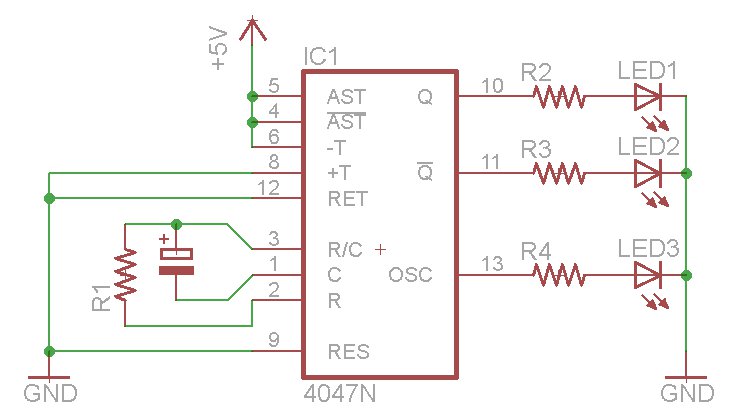
The oscillator output generates a signal that is approximately twice the frequency of Q. The other pins will be considered subsequently. In a brief video demonstration, LEDs are connected to all three outputs, illustrating the alternating behavior of Q...
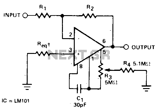
The required resistance (Req) may be zero or equal to the parallel combination of resistors R1 and R2 to achieve minimum offset. The circuit configuration described involves the use of two resistors, R1 and R2, connected in parallel. In a...

This circuit adjusts the gain of operational amplifier U1B in four distinct steps or segments. It is designed to achieve a linear output from various transducers at levels of 1%. Operational amplifier U1A serves as a buffering amplifier to...