
Laser power supply circuit
The DC power supply circuit for a helium-neon laser excitation system is designed to efficiently convert and regulate electrical energy for optimal performance in laser applications. The circuit begins with a power transformer (T1), which steps down the input AC voltage to a lower level suitable for further processing. The high-voltage transformer (T2) is crucial for generating the high voltages required for laser operation.
The series transistor regulator circuit plays a vital role in maintaining stable output voltage. It uses a combination of transistors (VT4 and VT5) configured for fine voltage adjustment, ensuring that the output voltage remains consistent despite variations in load conditions. The push-pull configuration of transistors (VT6 and VT7) in the regulator circuit enhances efficiency by allowing the circuit to handle higher power levels effectively.
The rectification process is accomplished using a bridge rectifier (VD1-VD4), which converts the AC voltage from the transformer into pulsating DC voltage. This voltage is then smoothed out by a filter capacitor (C1), providing a stable DC input to the regulator. The output from the regulator is then fed into the primary winding of transformer T2, where it is transformed into a higher voltage necessary for laser operation.
The high-voltage output from T2 is rectified again using another bridge rectifier (VD10-VD13) and filtered through a capacitor (C5) and an RC filter to ensure that the output is a clean DC signal. The current limiting resistor is a critical component that prevents excessive current flow to the laser tube, which could otherwise lead to damage. This resistor is carefully selected based on the specific discharge parameters of the laser system, typically falling within the range of tens to hundreds of kilohms.
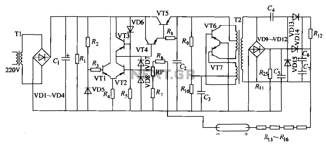
Overall, this circuit design ensures reliable operation of the helium-neon laser by providing a stable and safe power supply, which is essential for maintaining the performance and longevity of the laser system.DC power supply is a helium-neon laser excitation power supply currently used the most common form of power, there is shown a laser printer used in the road, Tl as power transf ormers, T2 is high-voltage transformer, the circuit consists of a series transistor regulator circuit, high-voltage rectifier, filter, limit the flow circuit and the steady flow circuit. This circuit is tested and functionable. alternating voltage VD1-VD4 bridge rectifier, filter capacitor Cl, output direct current voltage for series transistor regulator input voltage, VT4 VT5 composed of complex adjustment, the regulator circuit transistor VT6.
VT7 by common emitter connection for push-pull output, high voltage is applied to the primary winding of the transformer T2. High voltage output from the T2, ~ VD10-VD13 bridge rectifier, wind t, after c5 RC filter, and then through the current limiting resistor in series DC high voltage is applied to the electrodes of the laser tube, so that the lamp ignition point ignition, limiting resistor as a current limiting circuit, mainly used to protect the power supply and laser discharge tube, so that after the starter not to discharge current is too large, the resistance of a size generally in the tens to hundreds of kilohms kilohm range, depending on the discharge parameters may be.
Related Circuits
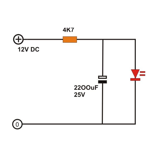
The light fader circuits described here share a common concept of creating a gradual "cool" switch ON and switch OFF effect for connected lamps. This means that each time the lights are activated, the result is a smooth transition...
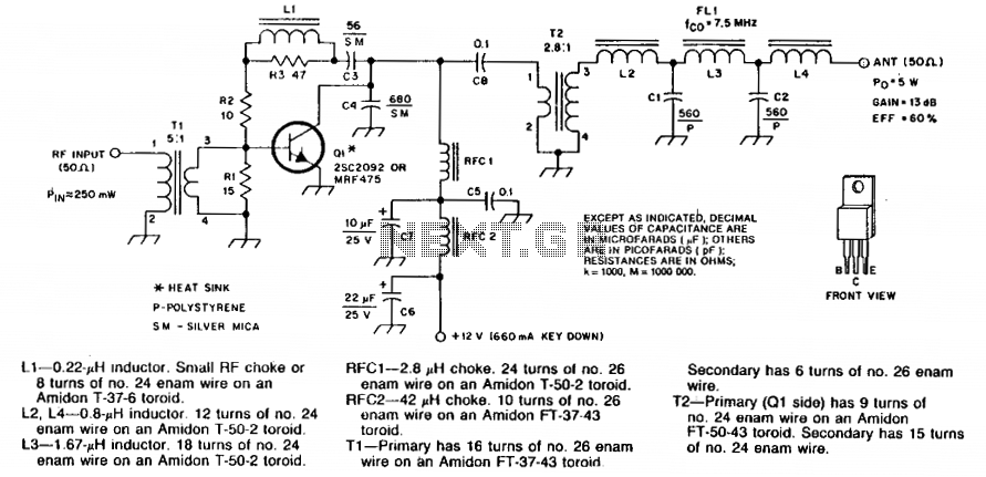
Numbered components are designated for PC-board layout purposes. C5 and C8 are disc ceramic capacitors. C6 and C7 are tantalum or electrolytic capacitors. R1, R2, and R3 are 1/4 W carbon composition resistors. Silver-mica capacitors may be substituted for...
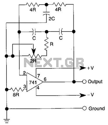
The quality of the sine wave depends on how closely the components in the twin-T network are matched in the operational amplifier's feedback loop. The twin-T network is a type of filter circuit commonly used in audio applications, signal processing,...
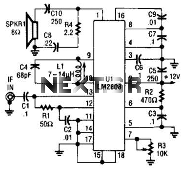
An LM2808 performs IF amplification of the 4.5-MHz sound subcarrier, limiting, detection, and audio amplification. If the center frequency must be changed, then change L1/C4. Audio output is 0.5 W. R3 is the volume control. The LM2808 is an integrated...
The TDA3567 is a monolithic integrated decoder designed for the NTSC color television standards. It incorporates all the necessary functions for the demodulation of NTSC signals. Additionally, it features a luminance amplifier and an RGB matrix amplifier. These amplifiers...
This document tells about one of my experiments with semiconductor laser modules. I bought one semiconductor laser for all kinds of experiments. This TIM202 module is a small (38x14x14 mm) semiconductor laser module, similar to those types used in...