
IO8 Module
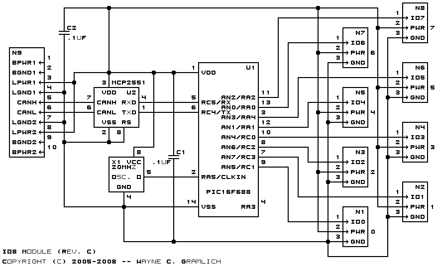
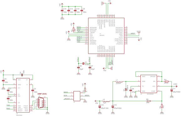
The circuit integrates a CAN bus communication system, utilizing the PCP2551 CAN bus transceiver (U2) to facilitate data transmission over the CAN protocol. The connection to the 2G-5 shrouded connector (N9) allows for a robust interface with external devices or systems, ensuring reliable signal integrity. The CAN bus signals are processed by the PCP2551, which converts the differential CAN signals into a format suitable for the PIC16F688 microcontroller (U1).
The PIC16F688 microcontroller serves as the central processing unit, handling both the reception and transmission of data via its UART interface. The UART signals are critical for serial communication, enabling the microcontroller to interact with other components or systems effectively. The microcontroller is interfaced with external components through a 1x3 polarized male header, which provides a convenient means for connecting additional circuitry or sensors. Each pin of this header corresponds to one of the analog inputs on the microcontroller, allowing for versatile input handling.
A half-size crystal oscillator (X1) is included in the design to provide a stable 20MHz clock signal, which is essential for the microcontroller's operation. The decision against using a resonator was made due to pin limitations; specifically, pins 2 and 3 of U1 are required for resonator connection, while pin 3 is allocated for an analog input (AN3). This careful selection of components ensures that the circuit functions optimally while adhering to the design constraints imposed by the microcontroller's pin configuration. Overall, this circuit demonstrates a well-thought-out approach to integrating CAN bus communication with a microcontroller, emphasizing reliability and functionality.The bus is connected to the 2G—5 shrouded conenctor N9. The two CAN bus signals are fed into the PCP2551 CAN bus transceiver U2. The output of U2 is fed to the UART transmit and receive signals on the PIC16F688 microcontroller U1. 8-pins of the U1 are connected to 1×3; polarized. 1" male headers. Each pin is connected to one of the anlog inpu ts on U1. A half size crystal oscillator (X1) is used to provide the reference 20MHz signal. A resonator could not be used since it requires pins 2 and 3 of U1, and pin 3 is needed for a analog input (AN3). 🔗 External reference
Related Circuits
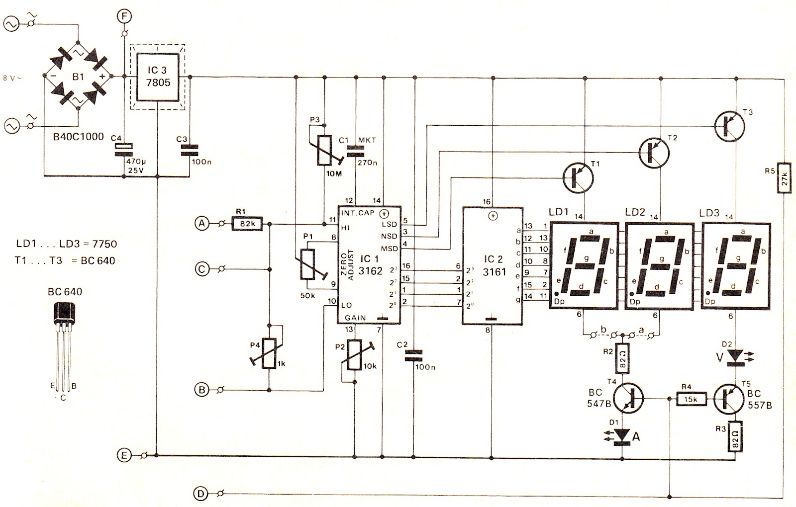
This voltage/current (V/I) display module is well-suited for integration into an existing DC power supply, providing precise readings of the set voltage or the current consumption of the load. The voltage measurement range features a decimal point indicator (LD3),...
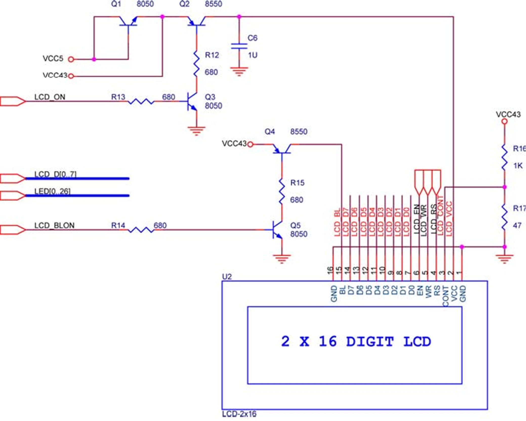
The LCD module is equipped with built-in fonts and can display text by sending the correct commands to the display controller known as HD44780. Comprehensive information regarding the usage of the display can be found in its datasheet. A...
The Rockwell Jupiter TU30-D140 is an OEM (Original Equipment Manufacturer) GPS receiver module designed for integration into larger systems, such as vehicle tracking systems, navigation systems, and time/clock references. It features a 12 parallel-channel all-in-view receiver, measures 4 by...
There is a vast array of TX and RX modules available for microcontrollers. The least expensive option identified was priced at $9.99, which is reasonable, although there are memories of encountering FM receiver modules in the past. The TX (transmitter)...
The first time a user signs into developerWorks, a profile is created. Certain information in the profile, including name, country or region, and company, is publicly displayed and will accompany any content posted. Users have the option to update...
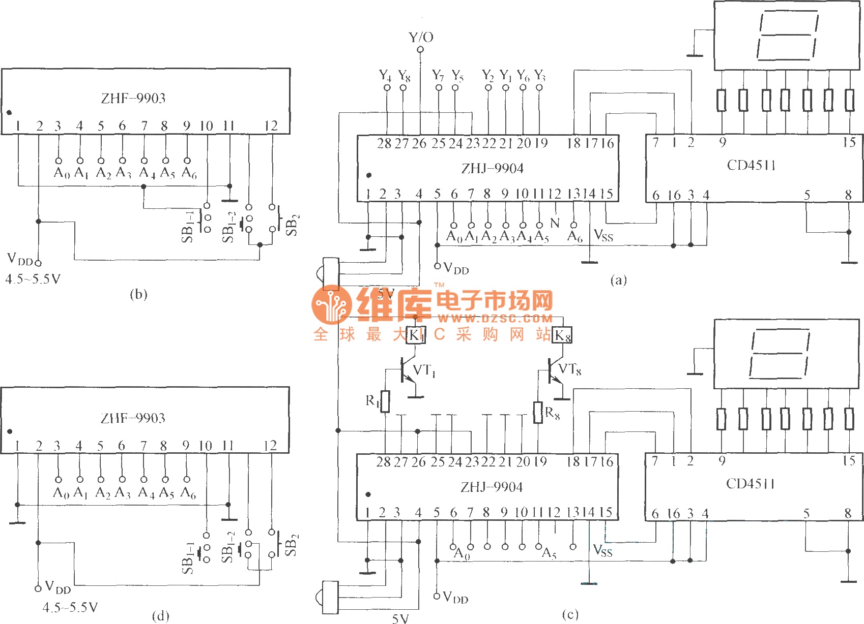
This is an eight-way signal remote control selection circuit composed of ZHJ-9904. It includes a remote control transmitter circuit, an eight-way switch control circuit, and a remote control transmitter. The eight-way signal remote control selection circuit utilizing the ZHJ-9904 is...
Warning: include(partials/cookie-banner.php): Failed to open stream: Permission denied in /var/www/html/nextgr/view-circuit.php on line 713
Warning: include(): Failed opening 'partials/cookie-banner.php' for inclusion (include_path='.:/usr/share/php') in /var/www/html/nextgr/view-circuit.php on line 713