
Digital Voltmeter and Ammeter Circuit Module

The V/I display module is designed for seamless integration into a DC power supply system, enhancing the usability and functionality of the power supply by providing real-time voltage and current monitoring. The module's architecture allows for easy adjustment and calibration, ensuring accuracy in measurements across a range of operating conditions. The presence of two distinct current measurement ranges allows the user to select the appropriate range based on the expected load, thus optimizing the resolution and accuracy of the readings.
The adjustment presets play a critical role in maintaining the precision of the module. P1 is essential for nulling the current measurement, compensating for any baseline current drawn by the module itself, which is crucial for accurate current readings. P3 serves a similar purpose for voltage measurements, ensuring that the displayed voltage accurately reflects the actual voltage at the load. P2 and P4 facilitate calibration of the full-scale readings, allowing the module to be fine-tuned to match the specifications of the power supply system.
The design incorporates an LED display, which provides clear visual feedback of the measured values. The activation of the decimal point indicator enhances readability, particularly in the voltage measurement mode. The use of a low-value sensing resistor minimizes the impact on the overall circuit, allowing for effective voltage division without significant loss of signal integrity.
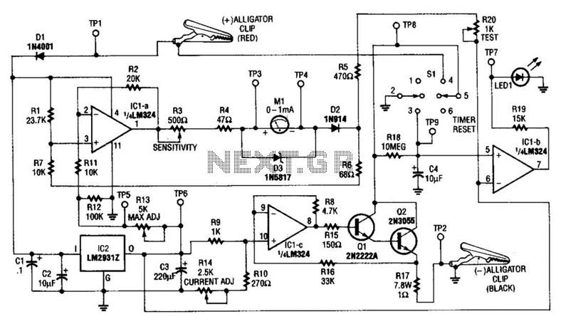
Powering the module from the unregulated supply voltage simplifies the design, eliminating the need for additional components such as a bridge rectifier, thus reducing complexity and potential points of failure. This design choice also ensures that the module can operate effectively within the specified voltage range, making it adaptable to various power supply configurations. Overall, the V/I display module is an efficient and effective solution for monitoring voltage and current in DC power supply applications.This V/I display module is eminently suitable for building into an existing DC power supply, where it gives a precise indication of the set voltage or the current consumption of the load. In the voltage range, the decimal point lights on LD3, and the resolution is therefore 100 mV Two current ranges are possible: 0-9.
99 A (link a) or 0-0. 999 (. 999 ) A (link b). These points should be adjusted in the above order. Two presets, P1 and P3, are required to ensure correct nulling of the module. P1 compensates for the quiescent current consumption of the regulator circuit in the supply. When voltage measurement is selected, P4-R1 attenuates the input voltage by a factor 100. Also, point D is pulled low so that the decimal point on the LS display, and the The sensing resistor has such a low value as to render the voltage divider ineffective. There are four adjustment points in the module: P1: current range nulling; P2: full-scale current calibration; P3: voltage range nulling; P4: full-scale voltage calibration.
The V/I display module is conveniently fed from the unregulated voltage available in the supply (max. 35 V) see points E and F in Fig. 2; bridge rectifier B1 may then be omitted. 🔗 External reference
Related Circuits
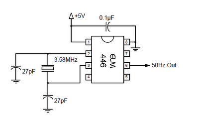
The ELM446 is an 8-pin digital divider integrated circuit that generates both 50Hz and 1Hz outputs from a common 3.58MHz NTSC colorburst crystal. The designer needs to supply only the crystal and two suitable loading capacitors, along with a...
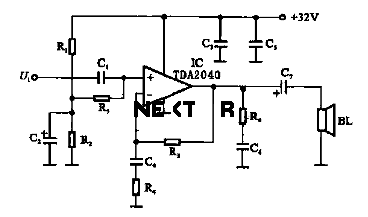
An integrated power amplifier TDA2040 is used in an OTL (Output Transformer-Less) power amplifier circuit, which operates with a +3V single supply as the working voltage. This circuit has a voltage gain of 30 dB (approximately 32 times magnification),...
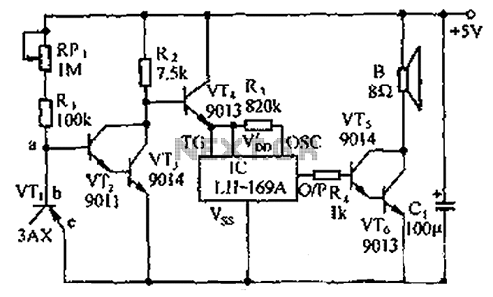
The circuit consists of a temperature sensor, electronic switches for temperature control, and a vocal language output system. During hot summer months, the central processing unit (CPU) of PCs frequently experiences overheating. The circuit, with VT1 positioned near the...
The search loop can be constructed in various ways; however, the method presented here should provide a solid foundation. Refer to Fig. 2 as a guide for assembling the loop. The loop should be made from non-metallic and moisture-resistant...
This circuit measures the cold cranking amps of a battery by discharging the surface charge and then assessing the internal resistance. This method provides a more accurate measurement than merely observing the instantaneous voltage drop under load. A constant-current...
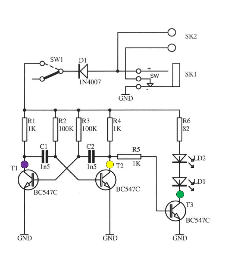
The schematic circuit presented below illustrates an infrared transmitter. The infrared beam is emitted in a nearly line-of-sight manner towards another device equipped with an infrared receiver. The displayed waveforms represent the output voltages from two intermediate stages (purple...