
iPod charger Schematic

The construction of a USB charger typically involves a few essential components: a power source, a voltage regulator, and USB output connectors. The power source can be a battery or an AC to DC adapter, which provides the necessary voltage and current to charge devices.
A common voltage regulator used in USB chargers is the LM7805, which steps down higher voltages to a stable 5V output suitable for USB devices. The input voltage range for the LM7805 is typically between 7V to 35V, allowing it to accommodate various power sources.
To design a basic USB charger circuit, the following components are required:
1. **Power Source**: An AC to DC adapter rated at 5V or higher (depending on the regulator used).
2. **Voltage Regulator**: An LM7805 or similar linear regulator.
3. **Capacitors**: Input and output capacitors (usually 0.33µF and 0.1µF respectively) are recommended to stabilize the voltage and reduce noise.
4. **USB Connector**: A standard USB Type-A or Type-B connector for output.
5. **Protection Diodes**: To prevent reverse polarity and protect the circuit from potential damage.
The circuit can be assembled on a breadboard for prototyping or soldered onto a PCB for a more permanent solution. The connections should be made as follows:
- Connect the input of the voltage regulator to the positive terminal of the power source.
- Connect the ground of the power source to the ground of the voltage regulator.
- Attach the output of the voltage regulator to the VBUS pin of the USB connector.
- Connect the ground of the USB connector to the common ground.
Testing the circuit involves measuring the output voltage with a multimeter to ensure it is stable at 5V. Once verified, the charger can be used to charge compatible USB devices safely. Proper heat dissipation methods should be considered, especially if the charger will be used for extended periods or with high current loads.First off I should mention that this is supplemental Instructable to the countless others that show you how to build a USB charger. I am assuming you.. 🔗 External reference
Related Circuits
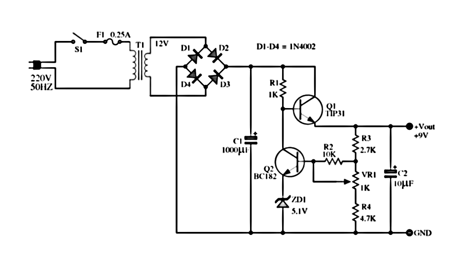
The power supply described utilizes a regulator composed of two NPN transistors. One transistor functions as the power regulator, while the other controls the output voltage. This power supply offers an adjustable output voltage range of 6-12 VDC. The...
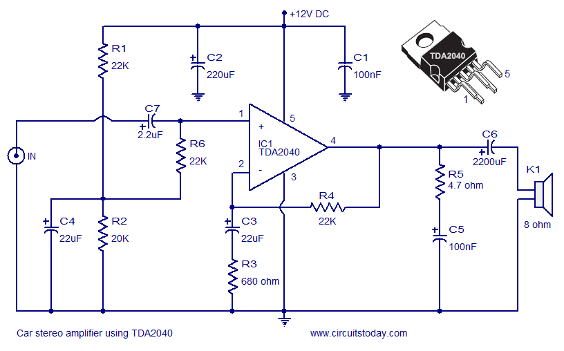
A car stereo amplifier circuit utilizing the TDA2040 is presented here. The TDA2040 is a monolithic integrated audio amplifier that functions in Class AB mode. This integrated circuit features built-in short circuit protection and thermal shutdown capabilities, and it...
The Accu charger circuit is straightforward and simple to construct, requiring no more than ten components. In addition to its ease of assembly, this charger circuit is also cost-effective and highly efficient. The circuit requires a power supply from...
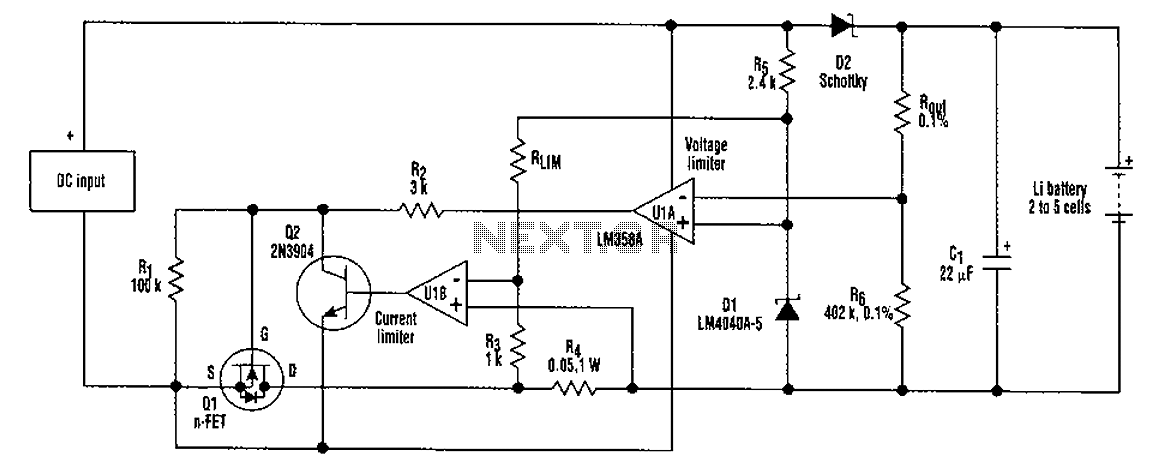
A universal rechargeable lithium battery circuit design, applicable to different battery types and numbers of batteries. This is because both the charger output voltage or current limit setpoint and the maximum charging current can be adjusted by simply changing...
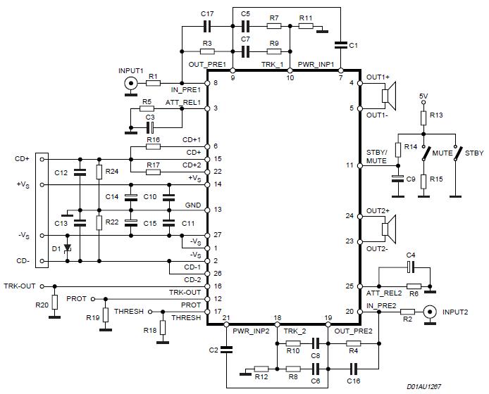
The Stereo Power Amplifier utilizes a 2x70Watt STA550 chip designed for audio power applications, featuring a BASH concept that allows connection to digital devices. This amplifier operates on a BTL (Bridge-Tied Load) system with a symmetrical power supply that...
This simple circuit makes it possible to monitor the charging process to a higher level. If you need more information then check out the LM3914 Datasheet. Final adjustments are simple and the only thing needed is a digital voltmeter...