
simple accu charger circuit
The Accu charger circuit's design typically includes a transformer, a rectifier, a filter capacitor, and a voltage regulator, along with additional components such as resistors and diodes to ensure proper operation. The transformer is essential for reducing the high voltage AC supply to a safer level suitable for charging batteries. The output from the transformer is then fed into a full-wave rectifier, which converts the AC voltage to DC voltage.
Following rectification, a smoothing capacitor is used to filter out any ripple in the DC output, resulting in a more stable voltage that can be used to charge the battery without causing damage. A voltage regulator may also be included to maintain a consistent output voltage, ensuring that the battery is charged efficiently and safely.
Additional components, such as protection diodes, can be added to prevent reverse polarity, which could potentially damage the circuit or the battery. The overall design emphasizes efficiency and simplicity, making it an ideal solution for basic battery charging needs. This circuit is particularly suitable for applications where cost and ease of use are critical, such as in small battery-operated devices or backup power supplies.The Accu charger circuit is very simple and easy to make, because it only requires a few components are also not more than 10 components. Besides easy charger circuit is also very cheap and very efficient. This circuit requires power supply from a transformer that comes from an AC voltage 220 and diuturunkan be 12-13 volts and then enter to-circuit an
d 12 Volt DC output allows for charging 12V battery 🔗 External reference
Related Circuits
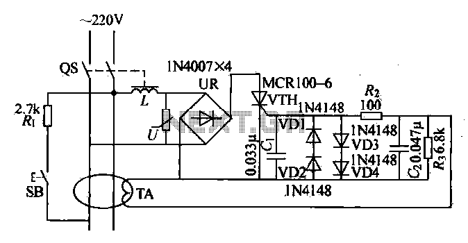
Current leakage protection is the most commonly used and effective leakage protection device. Current leakage protectors can be divided into electromagnetic and electronic types. The zero-sequence current transformer serves as the detection element, while electromagnetic leakage protection uses a...

The sensor must be positioned at an angle of approximately 30 to 45 degrees relative to the ground. This orientation facilitates the drainage of rainwater, preventing accumulation that could trigger the alarm due to water retention on the sensor....

A DC booster circuit is illustrated in the figure, which represents a step-up transformer circuit diagram. The step-up transformer (T) can be utilized to power small transistor radios. The winding ratio can be adjusted to achieve the desired output...
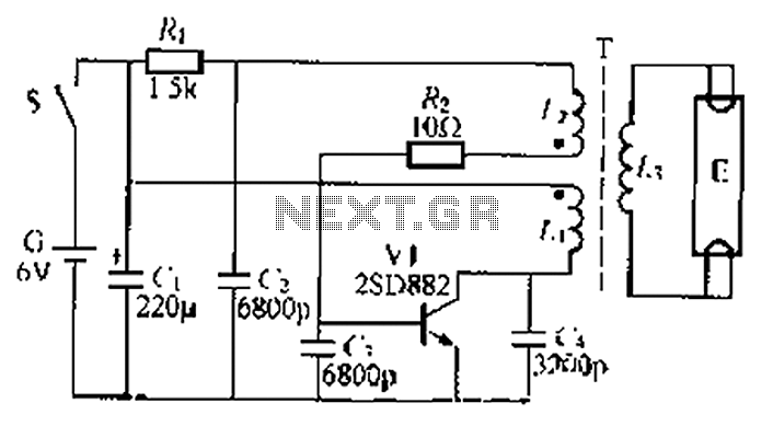
The circuit described is a battery-powered fluorescent lamp system designed for temporary emergency lighting during power outages. It utilizes a transistor (V7) and a boosting transformer (T) along with an inductive feedback oscillator to generate a high-voltage output. When...
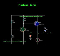
This is a flashing lamp circuit. This circuit operates with a 6V power supply. It can be installed on a bicycle or a car. A common transistor, the 2N3904, is used in this circuit. The flashing lamp circuit is designed...
The following circuit illustrates a Video and DVD Modulator in a VHF/UHF electronic diagram. Features include an oscillator that utilizes a transistor for high-frequency operation. The video and DVD modulator circuit serves to convert video signals into a format suitable...
Warning: include(partials/cookie-banner.php): Failed to open stream: Permission denied in /var/www/html/nextgr/view-circuit.php on line 713
Warning: include(): Failed opening 'partials/cookie-banner.php' for inclusion (include_path='.:/usr/share/php') in /var/www/html/nextgr/view-circuit.php on line 713