
iPod FM Transmitter

The iPod FM transmitter circuit is designed to operate within a specified frequency range, allowing users to broadcast audio wirelessly to FM radios. The circuit begins with the power supply, which is a 9V battery providing the necessary voltage for operation. The transistor (2N2219A) serves as the main amplifying component, enabling the modulation of the input audio signal.
The input audio is fed into the circuit at point c and is coupled through a resistor (R5) that functions as a trimmer to adjust the input signal level. This adjustment is crucial for ensuring that the audio signal is neither too weak nor too strong, which could lead to distortion or poor transmission quality.
Capacitor C6 is a trimmer capacitor that allows for fine-tuning of the transmitter’s output frequency. By adjusting this component, users can ensure that the transmitter operates on a frequency that is not occupied by other radio stations, thereby minimizing interference.
The antenna, constructed from a 70 cm copper wire, plays a critical role in radiating the modulated signal. The design specifies a spool (L1) made from silver wire, which acts as an inductor, enhancing the transmitter's performance. The specified dimensions ensure that the antenna and inductor are optimized for the desired transmission range of 100 to 150 meters.
Overall, this FM transmitter design is an effective project for individuals interested in exploring radio frequency transmission and audio broadcasting, combining basic electronic components to create a functional and practical device. Proper assembly and tuning of the components will yield a reliable transmitter capable of delivering clear audio over the specified distance.Building your own ipod FM radio transmitter. It works quite easy, there is a power switch on the bottom to turn it on and tune your radio and transmitter to the right frequency. For the antenna you can use a copper wire of 70 cm. The range of this FM transmitter is about 100 to 150 meters (500 feet). With R5 you can adjus t the input signal and with C6 you can tune your frequency. Transmitter is supplied by 9V battery. iPod FM Transmitter parts list: Transistor: T3. 2N2219a Capacitor: C3. 1 F/16 V C4, C5. 1 nF ker. C6 trimmer capacitor. 4-40 pF C7. 10 pF ker. Resistor: R5 Trimmer. 10 k © R6. 10 k © R7. 2, 7 k © R8. 1 k © Spool L1: Use a 10 cm long Silver wire. The diameter inside the spool should be 3 mm. 7 winds total Length of the spool should be 15 mm (f-g) The antenna is connected to the spool at 3mm from f a: + 9volt b: ground c: audio in Ground your audio input to b For the antenna you can use a copper wire (70 cm) With R5 you can adjust the input signal and with C6 you can tune your frequency. 🔗 External reference
Related Circuits
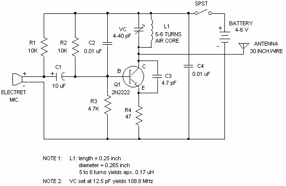
Wireless FM Transmitter. The site provides some explanation on how the circuit operates; however, there are uncertainties regarding certain components, including the electret microphone and the frequency modulation process. The electret microphone operates at a current of 200 µA,...
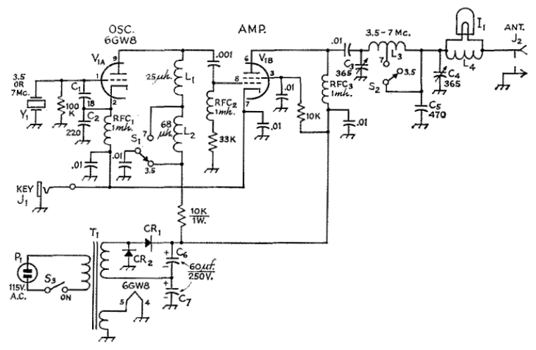
The circuit employs a 6GW8 triode-pentode in an oscillator-amplifier configuration that demonstrates an unconventional application of oscillator principles, coupled with a lack of attention to amplifier stability concerns. Consequently, this transmitter should not be replicated or operated without significant...

This is a design circuit diagram of a versatile FM transmitter. This circuit does not include a coil and is simple and easy to assemble. It operates based on gate logic concepts. The circuit features a buffer gate N1...
P1 acts as the volume level for the condenser microphone. For the FM transmitter, the coil will be small. It is recommended to use thin gauge enamel magnet wire. The diameter of the coil should be a couple of...
This house FM transmitter for your stereo or any other amplifier provides good signal strength up to a distance of 500 meters with a power output of approximately 200 mW. It operates on a 9V battery. The audio-frequency modulation...
This implementation is adapted to rebroadcast the output of a CD player, television receiver, or radio receiver. I use it so that I can move about the house and listen to my favorite programs without disturbing others. Within the...