
1.5V Battery FM transmitter

Many kinds of transistors will work fine in this application. After all, it's only an oscillator (frequency modulation is obtained by modulating the base-collector voltage, thereby modulating the depth of the depletion layer of the reverse-biased base-collector junction, which results in a change in capacitance at the collector, which results in a change in the resonant frequency of the collector circuit). I used a 2N4401 because I have a lot of them. I like 2N3904 and MPSH34 for this too.
Variations The objective of this design is to provide a simple, appliance-like low-power transmitter to rebroadcast audio. This transmitter does not have pre-emphasis, so it is not high-fidelity. It has sort of an "AM" sound for music and is fine for speech. Since there is no audio level control on the input, the audio level out of the CD player (or whatever you are driving it with) needs to be adjusted. Or, you can just add a 10k to 50k as an input level control, it's no big deal. This transmitter, as built, is not tunable once assembled; the coil is tweaked to the desired frequency, and everything is glued down. If you want to make one that's tunable, it might be easiest to reduce the 18 pF capacitor and put a small trimmer capacitor in parallel with the inductor (across the reduced value capacitor). Voltage variable capacitors would be a nice alternative to a mechanical variable capacitor but they don't offer much tuning range with only a 1.5V power supply.
The described transmitter circuit is designed for low-power audio transmission, capable of rebroadcasting signals from various audio sources such as CD players, televisions, or radios. It operates on a 1.5V power supply, typically provided by a single AA battery. The circuit employs a simple oscillator configuration utilizing a transistor, such as the 2N4401, which is common in low-power applications. The oscillator's frequency is determined by the inductor and capacitor values, with the inductor being adjustable by winding it on a suitable form and tuning it to a specific frequency on the FM band.
The design includes essential components such as a transistor, an inductor (coil), and a capacitor. The coil can be made using insulated wire, and its length and number of turns can be adjusted to achieve the desired resonance. The audio input is connected directly to the base of the transistor, modulating the base-collector voltage to achieve frequency modulation. The absence of an audio level control means that the input audio signal must be properly adjusted before feeding it into the transmitter.
For those seeking a tunable version of this transmitter, modifications can be made by incorporating a trimmer capacitor in parallel with the main tuning capacitor, allowing for fine-tuning of the frequency after assembly. This flexibility is beneficial for achieving optimal transmission quality in different environments. The circuit's simplicity and low power consumption make it suitable for casual listening without disturbing others, providing a practical solution for personal audio broadcasting within a limited range.This implementation is adapted to rebroadcast the output of a CD player, television receiver, or radio receiver. I use it so that I can move about the house and listen to my favorite programs without disturbing others.
Within and the house, I find that I can get 10 to 20 meters away from the transmitter with the small pocket FM receiver I carry in my shirt pocket. Your mileage may vary. The transmitter as built and pictured below (the transmitter is in the blob of hot melt glue on the end of the battery holder) does not have an on-off switch.
I put a 1.5 AA cell that was run down too far to run my CD player in this transmitter and it ran for over a month before I replaced it. The one in the transmitter at this moment has been running it continuously for over three months. Current draw is only about a milliamp with a new battery (assuming you don't have a super-high beta transistor in which case the theoretical limit is about 2.5 ma).
An on-off swich is not necessary, though it may satisfy an emotional need. Tips to get it working: Wind the coil on a 4 or 5 mm diameter Philips blade screwdriver or similar form then slip it off. I used some vinyl insulated #24 hookup wire as well as #30 enameled wire. In both cases, I played with the length of the coil to tune the transmitter to a dead spot on the FM band.
The coil is held in place with hot melt glue. If you don't have a spectrum analyzer or frequency meter, use a good-quality FM receiver to make sure its tuned where you think it is. While adjusting the coil, keep in mind that all superheterodyne receivers have images. If you find that two or more adjustments make the transmitter show up on the same spot on the receiver, it might be necessary to take a short walk and find out which adjustment drops out first -this would be the image, because the receiver's front end (if it has a tuned front end) will reduce its sensitivity to the image.
Many kinds of transistors will work fine in this application. After all, its only an oscillator (frequency modulation is obtained my modulating the base-collector voltage, thereby modulating the depth of the depletion layer of the reverse-biased base-collector junction, which results in a change in capacitance at the collector, which results in a change the resonant frequency of the collector circuit.). I used an 2N4401 because I have a lot of them. I like 2N3904 and MPSH34 for this too. . Variations The objective of this design is to provide a simple, appliance-like low-power transmitter to rebroadcast audio.
This transmitter does not have pre-emphesies, so it is not high-fidelity. It has sort of an "AM" sound for music and is fine for speech. Since there is no audio level control on the input, the audio level out of the CD player (or whatever you are driving it with) needs to be adjusted. Or, you can just add a 10k to 50k as an input level control, its no big deal. This transmitter, as built is not tunable once assembled, the coil tweaked to the desired frequency, and everything glued down.
If you want to make one that's tunable, it might be easiest to reduce the 18 pf capacitor and put a small trimmer capacitor in parallel with the inductor (across the reduced value capacitor). Voltage variable capacitors would be an nice alternative to a mechanical variable capacitor but they don't offer much tuning range with only a 1.5V power supply.
🔗 External reference
Related Circuits
The Muntz one-tube design can be significantly enhanced by incorporating an audio preamplifier stage. This modification increases sensitivity, allowing for full modulation with lower-level signal sources, such as certain older CD players and ceramic phono cartridges. Additionally, implementing negative...
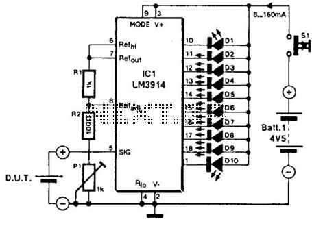
The LM3914A bar graph LED is utilized as a voltmeter for testing batteries. This circuit operates on a 4.5-V battery and compares the battery under test with an internally generated reference, established by resistors R1, R2, and potentiometer P1....
The following plans outline the construction of a compact tracking transmitter that can be detected using an FM broadcast band radio receiver. The transmitter operates on a battery voltage range of 3 volts to 9 volts and has a...
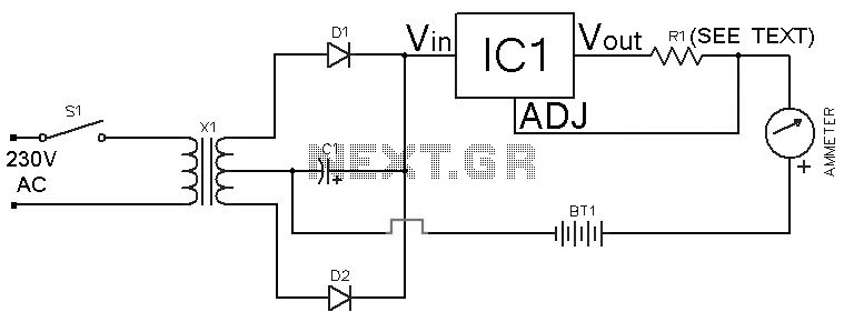
This Ni-Cd battery charger is a circuit utilizing the LM317 regulator IC. The design is straightforward and requires minimal components. By adjusting the value of resistor R1 between 1 ohm and 120 ohms, the charging current can be modified...
Sensitive FM Transmitter. Additional Notes: The default for the capacitors type is ceramic, preferably the NPO 1% type or equivalent. However, nothing critical is here; any type can be used. The sensitive FM transmitter circuit is designed to operate in...
Unlike many units, this battery charger continuously charges at maximum current, tapering off only near full battery voltage. In this unit, the full load. This battery charger is designed to operate with a continuous charging mechanism, maintaining the maximum current...