
Ir-Controlled Soldering Station

An infrared-sensitive phototransistor circuit designed for monitoring the temperature of a soldering iron operates on the principle of detecting infrared radiation emitted by the heated tip of the iron. The circuit is structured to minimize interference from ambient light by utilizing an opaque tube that directs the phototransistor's view solely to the soldering iron tip. This configuration ensures that only the infrared radiation from the iron is detected.
Incorporating an infrared filter is crucial for enhancing the accuracy of the temperature reading. The filter can be made from various materials, such as an old photographic negative or colored plastics, which selectively allow infrared wavelengths to pass while blocking visible light. This selection process helps to eliminate false readings that could be caused by external light sources.
The soldering iron is supported by a holder, which serves a dual purpose: it provides a safe resting place for the iron and ensures that the phototransistor can accurately detect the iron's temperature when it is in place. When the soldering iron is lifted from the holder, the phototransistor momentarily loses its target, resulting in a rise in temperature without immediate detection. The circuit is designed with a built-in lag time to accommodate this delay, allowing for a buffer period during which the iron can be returned to the holder before overheating becomes a concern.
This design is particularly beneficial in environments where soldering is frequently performed, as it provides a reliable means of monitoring the soldering iron's temperature, thus preventing potential damage from overheating while maintaining efficient operation. The careful selection of materials and components ensures that the circuit remains effective and durable over time. An IR-sensitive phototransistor is used to sense soldering-iron temperature. The phototransistor must see t he tip through an opaque tube to avoid stray light, and the phototransistor should preferably be fitted with an IR filter. An old photo negative, dark red plastic, or red or black glass can be used. The iron sits on a holder. When the iron is removed from the holder, the iron is not being viewed by the detector. The heat will increase, but the circuit has a lag time; if the iron is returned to its holder after each use, overheating should not be a problem.
Related Circuits
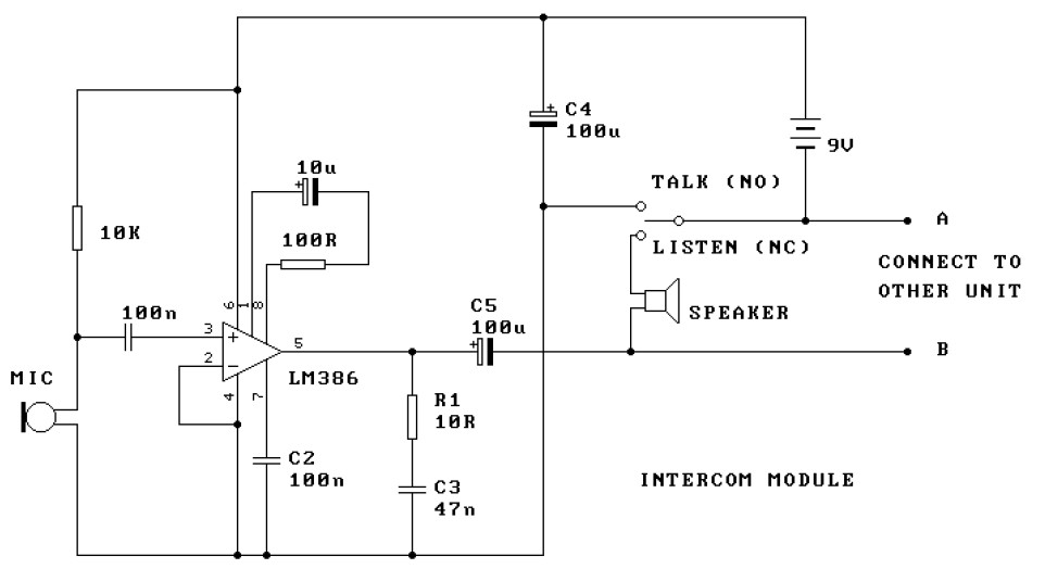
This is a two-station intercom system that operates using two wires connecting each intercom unit. Each unit is self-contained, equipped with its own battery, speaker, microphone, and amplifier circuit. An LM386 audio power amplifier is utilized, which is widely...
This article provides an overview of the R100 and MCR100 UHF repeaters. All information was obtained from a physical examination of the station, the programming software, and the R100 Instruction (and service) Manual, p/n 6881078E15, as well as the...

A certain part of this circuit is directly connected to the AC mains; therefore, do not touch it while in operation. It is essential to exercise extreme caution when handling the AC mains supply during the construction of this...
This is a simple and cost-effective inverter designed to power a small soldering iron (25W, 35W, etc.) in situations where a mains supply is unavailable. The circuit utilizes eight transistors. The inverter circuit operates by converting DC voltage from a...
A distribution substation is defined by the apparent power of the transformer and its configuration, which can be aerial, terrestrial, or underground. A distribution substation plays a critical role in the electrical power distribution network. It serves as a point where...
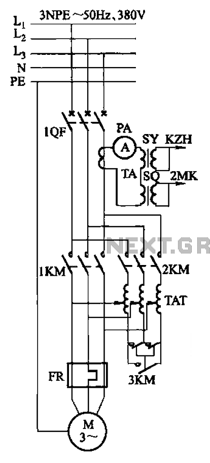
Autotransformer voltage starting, with an adjustable starting time of 30-60 seconds. It includes the SDJ electrode liquid level sensor of HJ-13 type, a pump control system box of HKD-21B type, 1MK level modules adopted by HKG-1SG type, 2MK start...