
ir decoder for general purpose

To implement an infrared (IR) control system for a variable resistor, it is essential to choose an appropriate IR decoder IC that can interpret signals from a standard IR remote control. Commonly used IR decoder ICs include the TSOP series, such as the TSOP1738, which can receive modulated IR signals and output a digital signal that can be processed by a microcontroller.
The circuit can be designed to interface the selected IR decoder IC with a microcontroller, such as an Arduino or a PIC microcontroller. The microcontroller will interpret the output from the IR decoder and control a digital potentiometer or a similar variable resistor circuit. The digital potentiometer can be adjusted by sending specific commands from the IR remote, allowing for the increase or decrease of resistance without the need for relays.
The first two pins of the microcontroller can be programmed to respond to specific IR signals that correspond to "increase" and "decrease" commands. The microcontroller will then adjust the digital potentiometer accordingly. The remaining pins can be utilized to control relays if additional functionalities are needed, such as switching between different circuits or loads based on the user's requirements.
The schematic will include the following components:
1. IR receiver module (e.g., TSOP1738)
2. Microcontroller (e.g., Arduino)
3. Digital potentiometer (e.g., MCP41010)
4. Power supply (as required by the components)
5. Optional relay module for additional control
Connections will be made as follows:
- The output pin of the IR receiver connects to an input pin on the microcontroller.
- The digital potentiometer will connect to the microcontroller through the SPI interface, allowing for control of the resistance value.
- If relays are included, they can be connected to other GPIO pins on the microcontroller, which can be activated based on additional commands from the IR remote.
This setup allows for flexible control of resistance values through IR signals, enabling a user-friendly interface without the mechanical complexity of relays for the primary function of adjusting resistance.Can i use the following circuit or is there any special IR decoder IC and schematics available If the decoder supports any remote is good and well, is it possible But i want to control variable resistor via IR without relays(Means not any different fixed resistance switching), Lets say first two pins used to reduce and increase resistance value. The remaining pins i can go with relays as per schematic. 🔗 External reference
Related Circuits
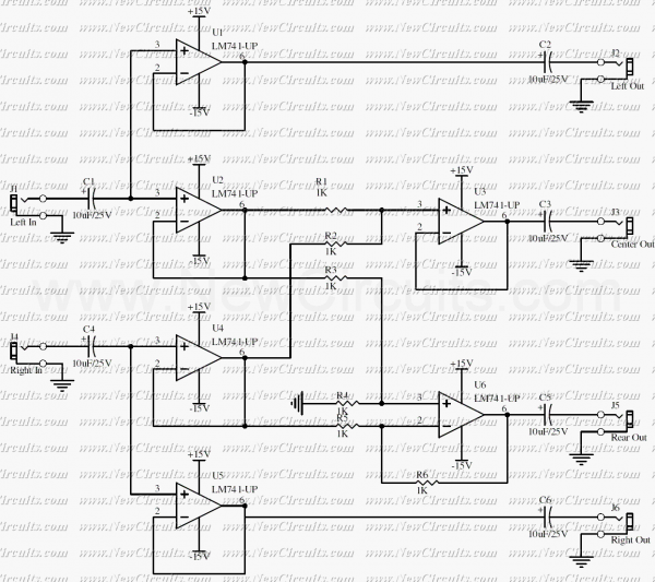
This is a simple surround sound decoder. Left & right outputs of a stereo tape or CD player can be connected to the circuit inputs and 4 outputs of the circuit can be connected to a surround power amplifier...
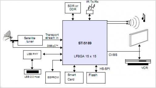
The STI5211 is a standard definition, full back-end processor designed for satellite set-top boxes, adhering to ATSC, SMPTE VC-1, DVB-S2, DIRECTV, DCII, and ARIB BS4 specifications. It delivers high performance for low-cost standard definition systems. Compared to the STi5202,...
The AD322 is an 8 amp G-Scale DCC decoder. The notes below may be beneficial to owners who wish to understand or repurpose ("hack") the decoder. It has a comprehensive set of functions that could easily be repurposed for...
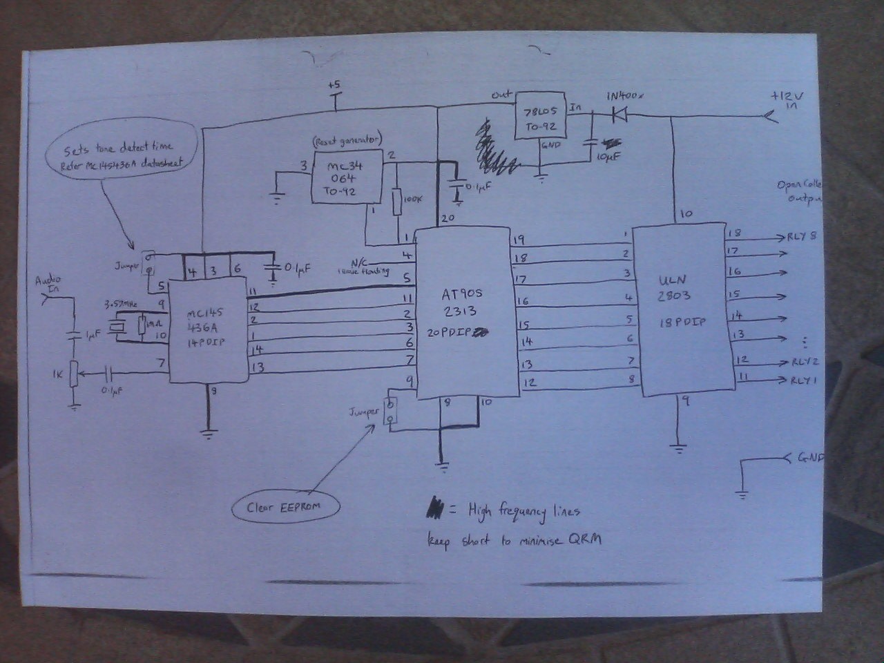
After a power interruption, all relays revert to their previous states, which are stored in non-volatile memory. A Motorola MC145436 DTMF decoder is utilized, clocked by a 3.58 MHz NTSC color burst crystal, providing a divide-by-8 clock output of...
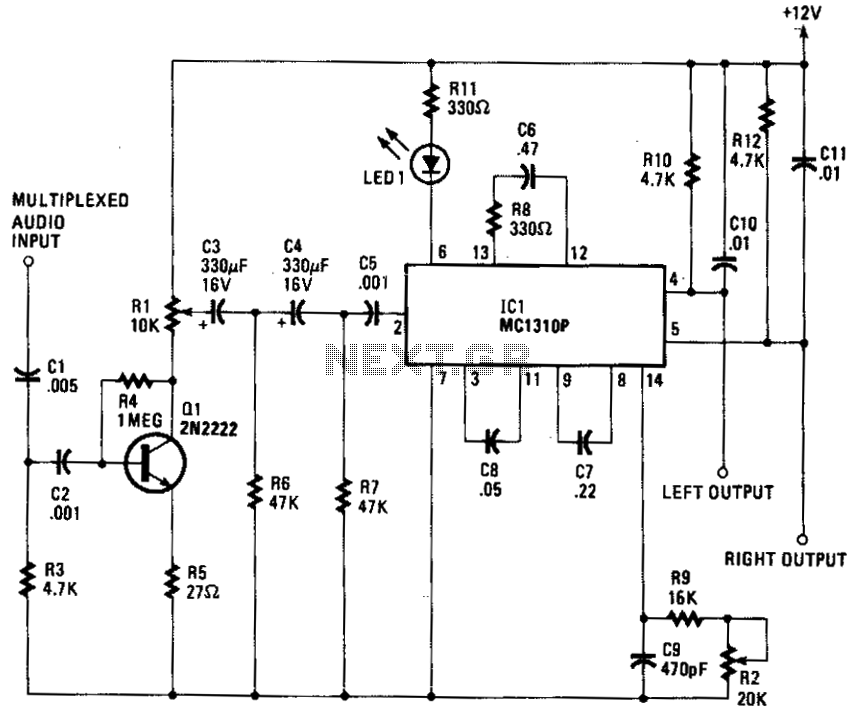
The composite input signal is amplified by transistor Q1 and is then connected to a high-pass filter consisting of capacitors C3 and C4, along with resistors R6 and R7. The filtered audio signal is subsequently sent to IC1, which...
This document provides the complete schematic for the circuit found on the AMZ Multi-Purpose PC Board. The example circuits do not utilize every component placed on the board; additional parts have been included to enhance flexibility and options. The...