
Stereo tv decoder
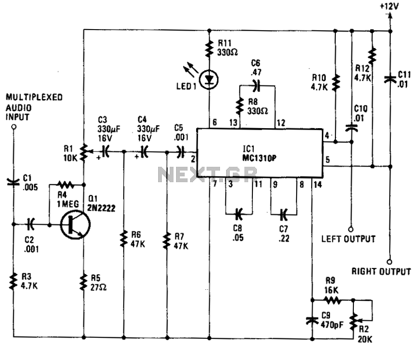
For an FM receiver application, the VCO would ordinarily operate at four times the 19 kHz pilot frequency (76 kHz). However, in this case, it operates at four times the 15.734 kHz pilot frequency of stereo television, resulting in a frequency of 62.936 kHz. The MC1310P divides the master VCO signal by two to generate a 31.468 kHz carrier frequency, which is utilized for detecting the left minus right (L - R) audio signal. This L - R signal undergoes standard FM detection, yielding two audio signals: left plus right (L + R) and left minus right (L - R). The decoder block within the IC performs the necessary addition and subtraction to extract the individual left and right audio signals. Resistors R10 and R11 form a de-emphasis network that compensates for the 75 µs pre-emphasis applied to the left channel, while resistor R12 and capacitor C11 serve the same purpose for the right channel.
The circuit operates effectively by ensuring that the audio signals are processed accurately for stereo output. The preamplification stage provided by Q1 enhances the signal strength, allowing for better performance in the subsequent filtering stage. The high-pass filter, composed of C3, C4, R6, and R7, is crucial in eliminating low-frequency noise, thus ensuring that only the desired audio frequencies are passed to the demodulator.
The MC1310P is a versatile component, and its ability to be configured for different frequencies makes it suitable for various applications beyond standard FM reception. The adjustment of the VCO frequency is critical for optimizing the demodulation of stereo television signals, which differ from typical FM broadcasts. The division of the master VCO output to generate the carrier frequency is a key feature that allows for effective detection of the stereo audio components.
The de-emphasis networks for both channels are essential in restoring the audio quality by compensating for the pre-emphasis applied during transmission. This ensures that the final output maintains fidelity and clarity, providing a high-quality listening experience. The careful design of each stage of the circuit from amplification to demodulation and de-emphasis contributes to the overall performance of the stereo audio system.The composite input signal is preamplified by transistor Ql and is then coupled to the high-pass filter composed of C3, C4, R6, and R7. The filtered audio is then passed to IC1, an MC1310P "Coilless Stereo Demodulator." That IC is normally used to demodulate broadcast-band FM signals, but by changing the frequency of its on-board VCO (Voltage Controlled Oscillator) slightly (from 19 kHz to 15.734 kHz), we can use that IC to detect stereo-TV signals.
A block diagram of the MC1310P is shown in Fig. 22-5. Notice that the components connected to pin 14 control the VCO's frequency, hence the pilot-detect and carrier frequencies. For use in an FM receiver, the VCO would run at four times the 19 kHz pilot frequency (76 kHz), but for our application, it will run at four times the 15.734 kHz pilot frequency of stereo TV, or 62.936 kHz. The MC1310P divides the master VCO signal by two in order to supply the 31.468 kHz carrier that is used to detect the L - R audio signal.
The L - R signal undergoes normal FM detection, and at that point we've got two audio signals: L + R and L - R. The decoder block in the IC performs the addition and subtraction to produce the separate left and right signals.
RIO and CIO form a de-emphasis network that compensates for the 75 /is pre-emphasis that the left channel underwent; R12 and Cll perform the same function for the right channel. 🔗 External reference
Related Circuits
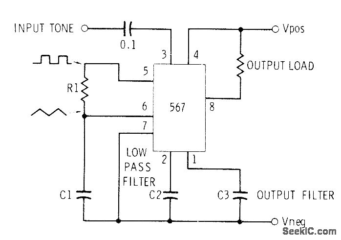
This circuit can be utilized for Touch-Tone decoding as well as for telephone line and wireless control applications using a single audio frequency. The operating center frequency is determined by components H1 and C1. The resistor R1 should be...
A lot of friends asked me to draw a more shrunk circuit 2-ch mixer, which will contain also, operation CROSSFADER. The circuits can be modified and added also other channels, repeating basic that I give. It can be added...
This device and all information contained on this website is for educational purposes only. This device must be used in conjunction with any and all local, provincial, and federal laws. It is the responsibility of the end user to...
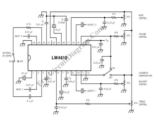
The LM4610 utilizes a DC signal to manage the tone (bass/treble), volume, and balance circuits. The benefits of employing DC control include the ability to operate in mono mode. The LM4610 is an integrated circuit designed for audio applications, specifically...
This is a simple stereo electret microphone preamplifier circuit. For optimal performance, it is recommended to use solid or film capacitors and metal film resistors. The circuit is based on a single IC, the LM358. It is straightforward, cost-effective,...
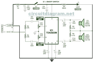
This is the circuit diagram of a USB-powered computer speaker, commonly referred to as multimedia speakers for PCs. The circuit features a single-chip design, operates on a low-voltage electrical power supply, is compatible with USB power from computers, and...