
Ir Detector
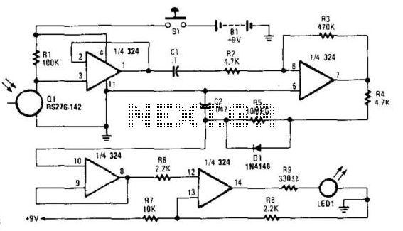
The circuit operates by detecting infrared (IR) light pulses emitted from remote controls or other IR sources. The primary component, Q1, is an IR photodetector that converts incoming IR light into an electrical signal. The output of Q1 is fed into operational amplifier U1A, configured as a voltage follower to ensure that the signal maintains its integrity without being loaded down by subsequent stages.
The differentiating network formed by capacitor C1 and resistor R2 serves to convert the continuous signal from the photodetector into sharp pulses, enhancing the detection of rapid changes in the IR light intensity. The output of this differentiating network is then amplified by operational amplifier U1B, which increases the amplitude of the signal for further processing.
Capacitor C2 is charged by the amplified pulses, and its voltage level is monitored by voltage follower U1C. This configuration allows U1C to provide a stable output that reflects the charge level of C2. The final stage of the circuit involves comparator U1D, which compares the sampled voltage against a reference level. When the voltage from C2 exceeds the reference, U1D activates LED1, indicating the presence of IR light pulses. The LED remains illuminated for a duration of two seconds, providing a clear visual indication of IR signal detection.
This circuit can be effectively used in various applications, including troubleshooting remote controls, testing IR-based alarm systems, and verifying the functionality of other IR-emitting devices. The design ensures reliable operation and clear feedback through the LED indicator, making it a practical tool for electronics testing and diagnostics. Useful for checking TV remote controls, IR-based alarm systems, and IR sources, this circuit causes LED1 to turn on for two sec onds in the presence of IR light pulses. UlA acts as a voltage follower for detector Ql. CI and R2 form a differentiating network and U1B acts as an amplifier for the pulses, which charges C2. Voltage follower U1C samples the voltage on C2 and drives comparator U1D, which switches LED1 on or off.
🔗 External reference
Related Circuits

This circuit monitors the duration of an incoming pulse. If the incoming pulse is shorter than the set value (VAR1), the output of U1B remains high. Values are provided for a 1 to 2 microsecond pulse. The described circuit functions...
This schematic diagram illustrates a 555 IC water level sensor and detector alarm circuit. The circuit is powered by the emitter current of the BC109C transistor. The 555 timer operates as an astable oscillator in this configuration. Under dry...
This page presents information on infrared - Across The Track train detection circuits. The circuits are designed around the LM339 comparator chip and can use a wide assortment of matched infrared - emitter / detector pairs. The basic circuit...
The core component of this DIY metal detector circuit is the CS209A. The metal detector is constructed with a single coil of 100 µH. The CS209A contains an oscillator that forms an LC circuit; the inductance of the coil...
This circuit gives out an alarm when its sensor is wetted by water. A 555 astable multivibrator is used here which gives a tone of about 1kHz upon detecting water. The sensor when wetted by water completes the circuit...
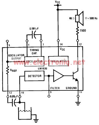
The LM1830 low-level detector can utilize an audio indication (speaker) or a visual indicator (LED - light-emitting diode) that activates when the level is too low. This low-level detector circuit generates a 500 Hz audio signal when the level...