
555 IC Water Level Sensor/Detector Alarm
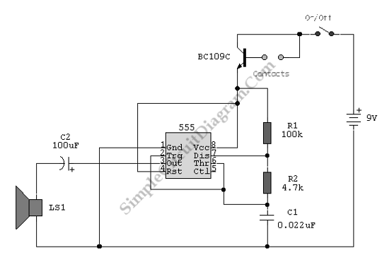
The circuit also features an alarm system capable of detecting any fluid with a resistance below 900K ohms between the maximum separation distance of the probes. A 4050B CMOS hex inverter is utilized to produce oscillation and detect the water level. This oscillation provides an alternating current (AC) source for the probe electrodes, which helps to prevent corrosion. Additionally, the MAXQ3210 is a powerful RISC microcontroller that supports battery-powered applications, enabling it to detect conditions and activate an alarm. The design includes a piezoelectric horn driver, a voltage regulator (5V to 9V), and an analog voltage comparator for enhanced functionality. Furthermore, the circuit can serve as a hot water level indicator, utilizing thermistors (NTC1-4) as sensors placed strategically to monitor the level of hot water in a tank. Another application of this technology is in a low-light level drop detector, which employs a self-biasing configuration to detect minute changes in light levels, commonly used in monitoring very low droplet rates. The collector of the transistor provides feedback that enhances the circuit's responsiveness to environmental changes.This schematic diagram below shows a 555 IC water level sensor/detector alarm circuit. This circuit is powered through the emitter current of the BC109C. 555 timer is used as astable oscillator in this circuit. When this circuit is under dry conditions the transistor will be fully off because it have no bias current. when the probes get wet, a sma ll current flows between emitter and base then the transistor switches on. The 555 osillator is enabled to sound because of a larger current flows in the collector circuit. Here is the schematic diagram of the circuit: An On/Off switch is provided and use a non-reactive metal for the probe contacts. We can use Gold or silver plated contacts from an old relay. But, a cheap alternative is to wire alternate copper strips from a piece of veroboard. These will eventually oxidize over, but the higher impedance caused by oxidization is not important because very little current is flowing in the base circuit.
the transistor is in emitter follower, so no base resistor is necessary. The current limit being the impedance at the emitter. [Circuit`s schematic diagram source: This schematic diagram shows a water level sensor/detector/monitor circuit. An alarm is also featured in this circuit. Any fluid with a resistance under 900K between the maximum separation distance of the probes will trigger this circuit.
A 4050B CMOS hex Continue reading †’. This water level sensor (detector) circuit uses a standard NAND logic gate to produce oscillation and to detect the water level. Oscillation is included inside this circuit to provide alternating current (AC) source for probe electrodes, to achieve a corrosion Continue reading †’.
The MAXQ3210 ia a powerful RISC microcontroller. This device have features and capabilities to make it compatible for battery-powered applications that detect a condition and sound on alarm. Piezoelectric horn driver, 5V to 9V regulator, and analog voltage comparator support Continue reading †’.
This is Hot Water Level Indicator circuit. This circuit can be used to monitor level of hot water in a tank. This circuit is simple and inexpensive. this circuit uses thermistors NTC1-4 as the sensor that is placed spread over Continue reading †’. This is a circuit of Low-Light Level Drop Detector. This circuit utilize self-biasing configuration to detect small changes in light level. This circuit usually used in monitoring very low droplets rates. The collector of the transistor gives feedback that is Continue reading †’. 🔗 External reference
Related Circuits
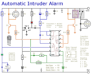
This is a simple single-zone burglar alarm circuit. Its features include automatic exit and entry delays and a timed bell/siren cut-off. It is designed to be used with the usual types of normally-closed input devices such as magnetic reed...

A low-cost, high-performance programmable home security system utilizing a few LDRs as input sensors. When the sensors are triggered, the system can dial a user-specified phone number using a built-in DTMF generator and activate a high-power audio alarm and...
The circuit presented here can convert a single-ended supply voltage into a balanced set of supply voltages. This is achieved without the use of difficult-to-obtain, exotic integrated circuits. All components utilized in the circuit are common and likely available...
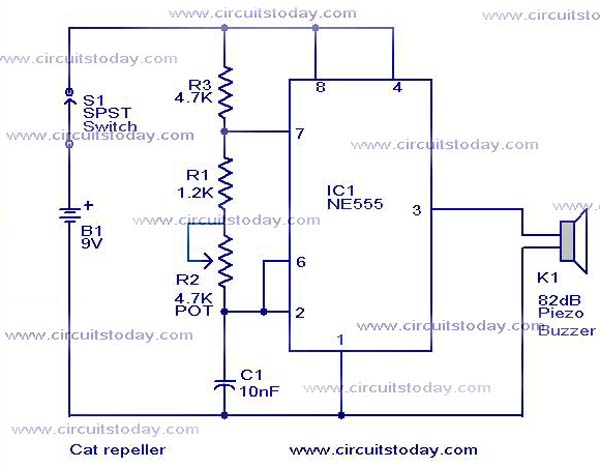
This cat and dog repeller circuit is designed to deter animals from specific areas. The circuit utilizes ultrasonic sound, which is known to provoke a strong response in many animals, particularly cats. The design features an astable multivibrator configuration...
A passive light-emitting diode output level indication circuit. This circuit utilizes a light-emitting diode (LED) to provide a visual indication of the output level from a given source. The design is characterized by its passive nature, meaning it does not...
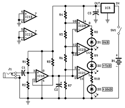
No setup is required: if correct values are used for resistors R3 to R7, LED D1 will illuminate at 0 dB input (0.775V RMS), LED D2 at +5 dB input (1.378V RMS), and LED D3 at +10 dB (2.451V...
Warning: include(partials/cookie-banner.php): Failed to open stream: Permission denied in /var/www/html/nextgr/view-circuit.php on line 713
Warning: include(): Failed opening 'partials/cookie-banner.php' for inclusion (include_path='.:/usr/share/php') in /var/www/html/nextgr/view-circuit.php on line 713