
IR-Link Temperature Sensor Allows Isolation of the Temp Sensor

The circuit operates by utilizing an infrared (IR) transmitter and receiver pair to wirelessly transmit temperature readings from a sensor to a receiving unit. The temperature sensor, which could be a thermistor or an RTD (Resistance Temperature Detector), is connected to a microcontroller that processes the temperature data. The microcontroller converts the analog signal from the temperature sensor into a digital format and encodes it for transmission.
The IR transmitter, typically an IR LED, is driven by a modulated signal generated by the microcontroller. This modulation helps to minimize interference and allows for reliable data transmission over the IR link. The encoded temperature data is transmitted in bursts, which can be demodulated and decoded by the IR receiver at the receiving end.
The IR receiver, commonly a photodiode or phototransistor, detects the modulated IR signal and converts it back into an electrical signal. This signal is then fed into another microcontroller or processing unit, which decodes the received data and displays the temperature reading on an output device, such as an LCD screen or a computer interface.
Isolation of the temperature sensor from the receiving unit is achieved through the IR communication, which eliminates the need for direct electrical connections. This design enhances safety and allows for remote monitoring of temperature in environments where electrical connections may pose a risk or where it is impractical to run wires. The circuit can be powered by batteries or a low-voltage power supply, making it suitable for portable applications. Overall, this IR temperature transmission circuit is effective for applications requiring non-contact temperature monitoring and data transmission.A circuit is described that transmits temperature data over an IR link. This allows isolation of the temperature sensor.. 🔗 External reference
Related Circuits

This design outlines a sensor circuit that utilizes an LED as a light sensor. The operational control and amplification of the output are managed by a 1458 integrated circuit (IC), which functions as an operational amplifier (op-amp). The circuit...
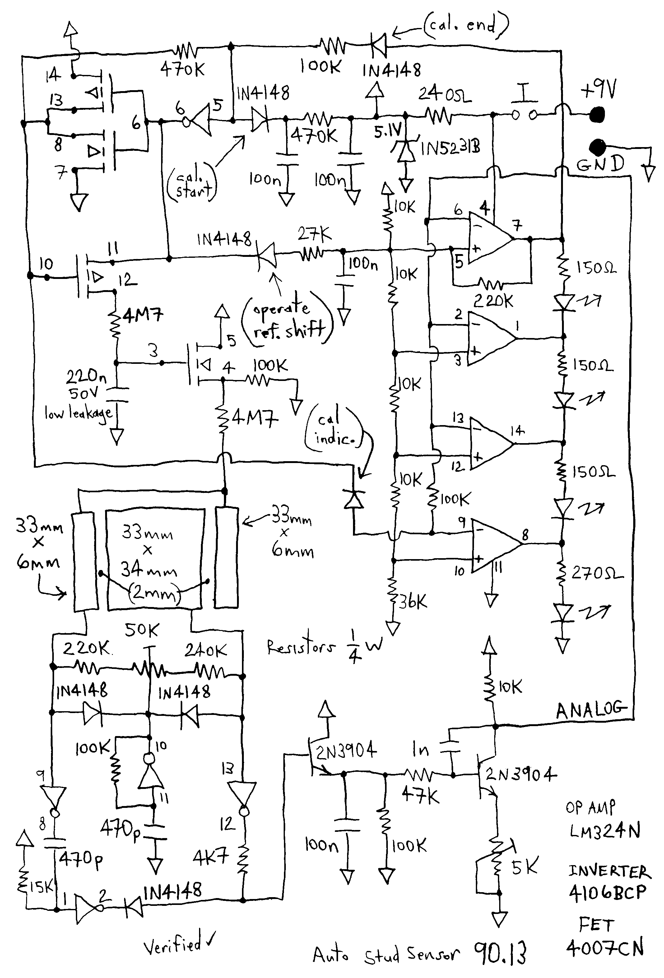
This thing is a very nifty capacitive sensor. For you europeans, this little gem is used in north america mostly for detecting wooden beams behind drywall or plaster. I'll take one of these over the new design any day,...
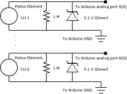
The piezo element is connected solely to Channel 1 (Arduino A[0] port). Channels 1 through 6 are linked to female mono jacks, with the ground (GND) wiring arranged in series from jacks 1, 2, and 3, continuing to the...
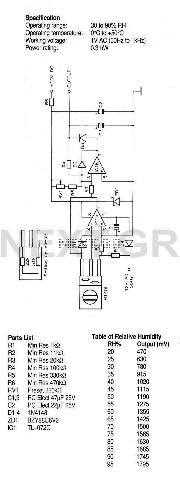
A humidity sensor with temperature compensation built-in. Never apply a DC voltage to the sensor, even measuring the sensor with an ohmmeter will damage the device, always ensure that an AC voltage is applied. Avoid condensation, freezing, dust, mist,...
A compact thermal control solution for Dense Wavelength Division Multiplexing (DWDM) laser modules can be implemented using a MAX8520/21 and a single operational amplifier. The proposed thermal control solution utilizes the MAX8520 or MAX8521, which are highly efficient, low-dropout linear...
A company has developed an intelligent temperature monitoring system using the ATMET 89C51 microcontroller. This system automatically records temperature data for a three-phase power supply, including high temperature and other relevant data, functioning as a black box. The ATMET...