
sensor Arduino analog signal read problem

The circuit design involves a piezo element connected to the first analog input of an Arduino microcontroller, specifically the A0 pin. This configuration allows the Arduino to monitor the piezo element's output, which can be used for various applications such as detecting vibrations or pressure changes. The remaining channels (A1 to A5) are set up to read from additional sensors or inputs, connected through female mono jacks. Each channel's ground connection is designed in a daisy-chain manner, ensuring that all channels share a common ground, which is critical for accurate sensor readings.
The software component of the system is structured to initialize an array for sensor readings and a boolean variable to track whether any reading exceeds a predefined threshold. The setup function establishes a serial communication link at a baud rate of 9600 bps, enabling real-time data transmission to a connected computer or display device. In the loop function, the code continuously reads values from the analog inputs, storing them in the sensor reading array. A for-loop iterates through the readings, checking if any value surpasses the defined signal level of 10. If this condition is met, the threshold variable is set to true, prompting the program to output the current sensor readings to the serial monitor.
This design allows for effective monitoring and analysis of multiple analog inputs, providing valuable data for applications ranging from simple sensor readings to more complex data logging and event-triggered actions based on sensor thresholds. The error messages indicate potential issues with the readings from certain channels, suggesting that further investigation may be needed to ensure reliable operation across all channels.The piezo element is only connected to Channel 1 (Arduino A[0] port). The channels Ch 1 Ch 6 are connected to female mono jacks and the ground(GND) wiring is in series from jack 1, 2 and 3 so on. till the Ch 6 end to the Arduino GND port. Taped 3 times 787 0 0 0 0 0 191 0 0 0 0 0 19 0 0 0 0 0 937 123 63 5 0 0 < ch2, ch3 ch4 ERROR !> 86 0 0 0 0
0 13 0 0 0 0 0 507 83 126 16 8 0 < ch2, ch3, ch4 ch5 ERROR !> 21 1 1 0 0 0 < ch2, ch3 ERROR !> 0 0 18 0 0 0 < ch3 ERROR !> const int singnalLevel = 10; boolean treshold = false; int sensorReading[6]; void setup() { Serial. begin(9600); } void loop() { int sensorReading[6] = {0, 0, 0, 0, 0, 0}; boolean treshold = false; sensorReading[0] = analogRead(A0); sensorReading[1] = analogRead(A1); sensorReading[2] = analogRead(A2); sensorReading[3] = analogRead(A3); sensorReading[4] = analogRead(A4); sensorReading[5] = analogRead(A5); for (int index = 0; index <= 5 ; index+) { if(sensorReading[index] > singnalLevel){ treshold = true; } } if(treshold){ for (int index = 0; index <= 5 ; index+) { Serial.
print(sensorReading[index]); Serial. print(" "); } Serial. println(); } delay(1); } 🔗 External reference
Related Circuits
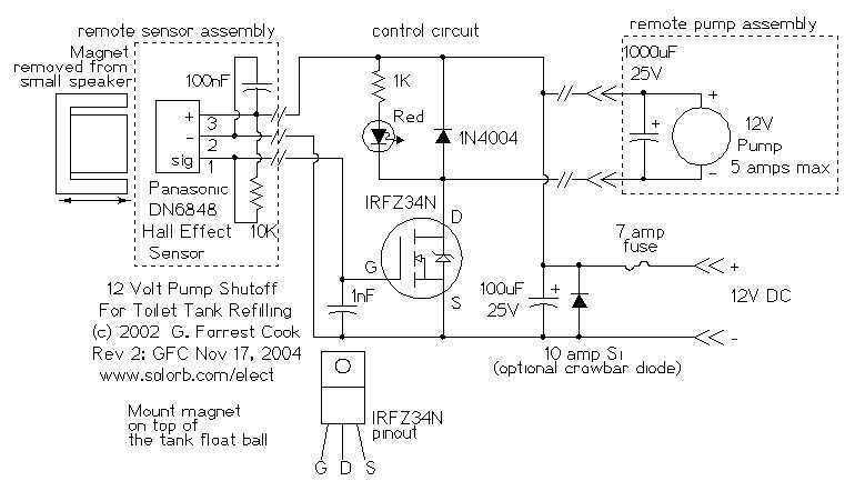
The 12 Volt power in my application comes from a small solar power system; it may also be provided by a suitable wall-wart DC power supply. The cistern is located below the toilet tank; the pump moves the water...
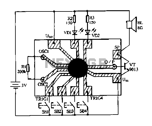
Constantly changing light and sound analog controller circuit 04 The circuit designated as the "Constantly Changing Light and Sound Analog Controller Circuit 04" is designed to modulate both light and sound outputs in a dynamic manner. This type of...
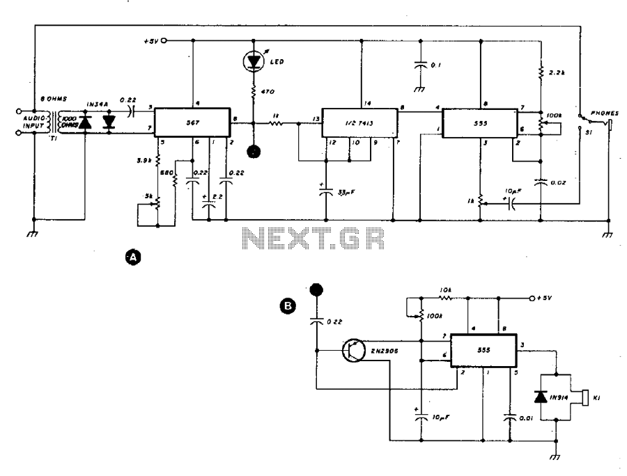
This circuit provides interference rejection for the continuous wave (CW) operator. The 567 phase-locked loop (PLL) is configured to respond to audio tones ranging from 500 to 1100 Hz. A Schmitt trigger is employed to mitigate the weighting effect...
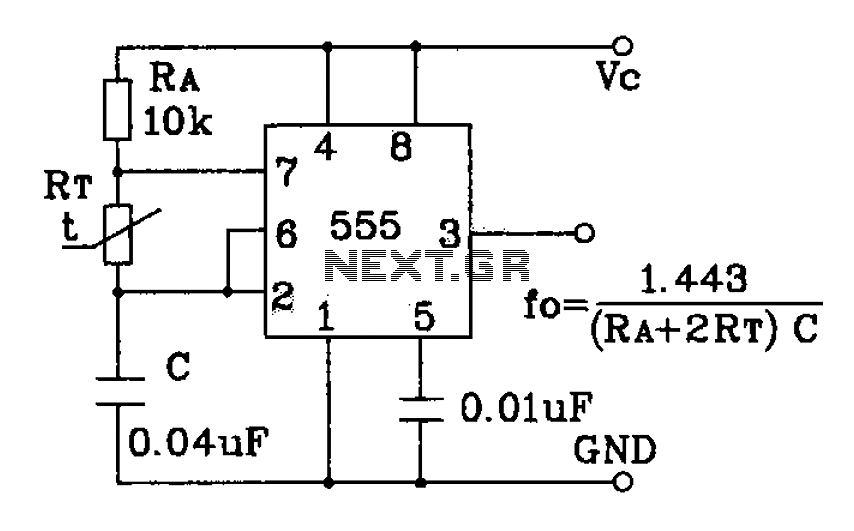
555 precision temperature sensor with temperature frequency converting circuit diagram consisting of: The 555 precision temperature sensor operates by converting temperature variations into frequency signals. This circuit typically utilizes a 555 timer IC configured in astable mode to generate...
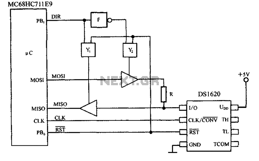
This circuit features a three-wire serial interface for smart temperature sensors, specifically the DS1620, along with an SPI bus interface circuit. The DS1620 is a high-accuracy digital temperature sensor that communicates over a three-wire interface, which consists of a data...
This circuit provides a visual 9-second delay using a 7-segment digital readout LED. When the switch is closed, the CD4010 up/down counter is preset to 9, and the 555 timer is disabled with the output held high. The circuit utilizes...