
Ir Receiver I
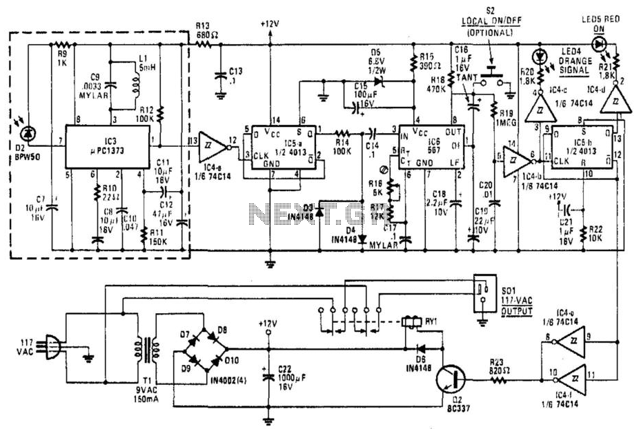
The circuit operates effectively as an IR remote control receiver by utilizing the uPC1373 preamplifier to amplify incoming IR signals. The tuned detector is critical for isolating signals within the 30-to-40 kHz range, ensuring that the receiver is sensitive to the modulation frequencies typically used in remote control applications. The automatic gain control feature helps maintain a consistent output level despite variations in the strength of incoming signals, which is essential for reliable operation.
The demodulated signal is processed through a Schmitt trigger (IC4A) to produce a clean square wave, which is then fed into a dual "D" flip-flop (IC5A) to divide the frequency by two, generating a 750 Hz output. The clipping stage involving diodes D3 and D4 ensures that the signal remains within a manageable voltage range for subsequent processing stages.
The 567 tone decoder (IC6) is pivotal for frequency detection, as it determines if the incoming signal frequency matches its internal reference. When a valid signal is detected, it triggers the output to go low, signaling the presence of a valid command from the remote control. This low output is then used to activate additional logic components, including another Schmitt trigger and a second "D" flip-flop (IC5B), which further processes the signal.
The final output from the flip-flop drives a transistor (Q2) that controls a relay, allowing the circuit to switch on or off an external device based on the received IR signal. The inclusion of the LED indicator (LED4) provides visual feedback to the user, confirming the reception of a signal. Overall, this circuit design effectively integrates various components to create a responsive and reliable IR remote control system. This receiver is built around a uPC1373 IR remote-control preamplifier, a sensitive 30-to-40 kHz tuned detector, an automatic gain control, a peak detector, and an output waveshaping buffer. The demodulated signal from the preamp stage is sent to IC4A, a 74C14 Schmitt trigger. The squared-up 1 500-Hz signal is then sent to the clock input of IC5A, half of a 4013 dual "D" flip-flop. That 750-Hz signal is clipped to approximately 0.7-V p-p by diodes D3 and D4. The clipped signal is then fed to IC6, a 567 tone decoder. The output of that IC goes low whenever the frequency of the signal fed to it is within the lock range of its internal VCO.
When IC6 detects a signal of the proper frequency, pin 8 goes low. The output signal is fed through another Schmitt trigger (IC4B), which drives another "D" flip-flop, IC5B. Schmitt trigger IC4B also drives IC4C, which in turn drives LED4, SIGNAL, which lights up whenever a signal is received.
The Q output of IC5B drives two parallel-connected inverters. IC4C and IC4F turn transistor Q2 on when Q goes low. That transistor energizes the relay; its contacts switch the controlled device on and off. 🔗 External reference
Related Circuits
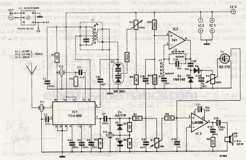
The selection is made with ceramic filters. This 27 MHz receiver operates with an intermediate frequency of 455 kHz. The circuit employs ceramic filters for signal selection, which are known for their high selectivity and low insertion loss. Ceramic filters...
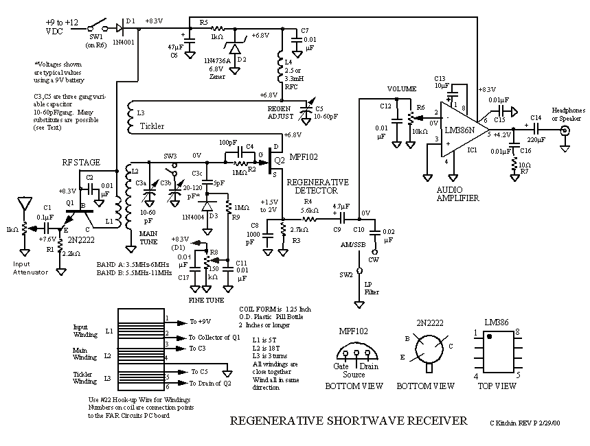
A regenerative radio receiver is known for its simplicity, weak signal reception, inherent noise-limiting and automatic gain control (AGC) action, as well as its immunity to overloading and spurious responses. The regenerative radio receiver, often referred to as "regen,"...
To comprehend the interconnections between the following circuits, it is essential to first review the concept chapter. It is at the discretion of the user to select one or two of these circuits for personal development. The discussion begins...

The TEA5551T monolithic integrated radio circuit can be utilized to design an AM radio receiver, intended for use as a portable radio receiver with headphones. The TEA5551T radio receiver circuit encompasses all necessary components for a complete AM receiver,...
This circuit enables the generation of audio musical notes that can be heard from a distance of up to 10 meters. It consists of two main components: an infrared (IR) music transmitter and an IR music receiver. The IR...
The tuned circuit consists of a variable capacitor and fixed air spaced coil. For the coil, wound between 10 and 20 turns of wire on an empty tube of around 1.5 inches diameter. The turns were spaced so that...