
Circuit diagramms of the 144 SBB/RX - Receiver
The 6 MHz oscillator circuit is designed to achieve optimal frequency stability over extended periods. The use of multiple buffer stages serves to isolate the output frequency from variations in load conditions, ensuring consistent performance. This design consideration is critical in applications where precise frequency control is required, such as in communication systems or signal processing.
In the 36 MHz oscillator configuration, the presence of a shunt diode has been identified as a source of increased phase noise, which can adversely affect the oscillator's performance. Therefore, eliminating the diode from the circuit is recommended to maintain signal integrity. The coupling capacitor, originally rated at 22pF, can be enhanced to 27pF to expand the tuning range, allowing for finer adjustments in frequency output.
The resonator section, which includes components like the BB204 and J310, should utilize capacitors that exhibit zero temperature drift characteristics. This selection is vital for maintaining frequency stability across varying environmental conditions. The trimming capacitor, typically a silver-air type, is employed to fine-tune the oscillator frequency. While a higher-quality trimmer is preferred for optimal performance, using a more economical alternative will not significantly compromise long-term stability due to the relatively minor role this component plays in the overall circuit operation.
In summary, careful consideration of component selection and circuit design is essential for achieving desired frequency stability and performance in oscillator circuits. These insights are crucial for engineers and developers seeking to implement reliable and efficient oscillators in their designs.In order to understand how the following circuits are connected to each other you have to read the concept chapter first. Of course it is up to you to take just one or two of these circuits for your own developments. Lets start with the 6 MHz oscillator. The highest priority in this circuit is its long term frequency stability. You might be surpri sed about the many buffer stages. I tried to make sure that the output frequency is 100% independent of the circuit load (and it seems that I even overdid it a little bit). Now we will have a look at the 36 MHz oscillator. It turned out that the shunt diode increase the phase noise. Therefore I recommend to skip it. The 22pF coupling capacitor can be increased to 27pF which gives a bit more tuning range. All capacitors in the resonator (i. e. between the BB204 and the J310) should be "zero temperature drift" types. The trimming capacitor is a silver-air-trimmer, but the long term stability will not decrease a lot if you use a cheap trimmer since the influence of this capacitor is quite small.
🔗 External reference
Related Circuits
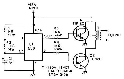
This low-power 25-watt power inverter circuit utilizes only nine electronic components. The inverter converts a DC input voltage ranging from 10V to 16V into a 60Hz, 115V square-wave power output, capable of powering AC electronic devices up to approximately...
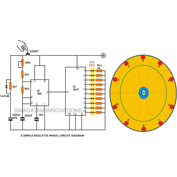
A simple circuit for a 10 LED roulette wheel is presented. Pressing the button initiates the LEDs in a rotational sequence that starts at full speed and gradually decelerates until it halts at a randomly selected LED. The randomness...
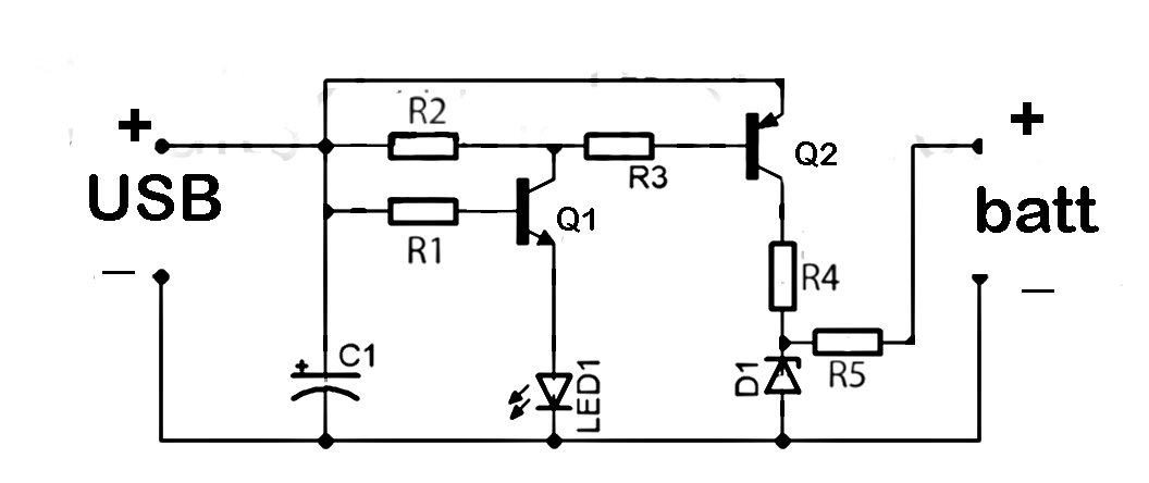
This document discusses the series used in USB connections for charging batteries. The output voltage ranges from 4.7 volts to 5 volts DC, which is suitable for charging mobile phones and other battery types. The circuit described enhances the...
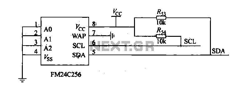
The FM24C256 is utilized as a slave interface circuit in an I2C bus configuration, with the address format specified in Table 27-3. The address pins A2, A1, and A0 are set to low; however, for extended storage capacity, adjustments...
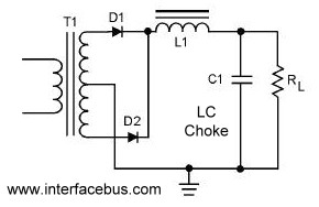
A circuit that utilizes both positive and negative alternations in an alternating current to generate direct current. There are two types of full-wave rectifier circuits: one that employs two diodes and requires a center-tapped transformer, and another that uses...
This controller consists of three pairs of LED sensors arranged in a 3G-bridge configuration. The driver is capable of operating three actuators, with the motors connected in a Delta configuration. The apexes of the delta are linked to the...
Warning: include(partials/cookie-banner.php): Failed to open stream: Permission denied in /var/www/html/nextgr/view-circuit.php on line 713
Warning: include(): Failed opening 'partials/cookie-banner.php' for inclusion (include_path='.:/usr/share/php') in /var/www/html/nextgr/view-circuit.php on line 713