
Ir Receiver Ii
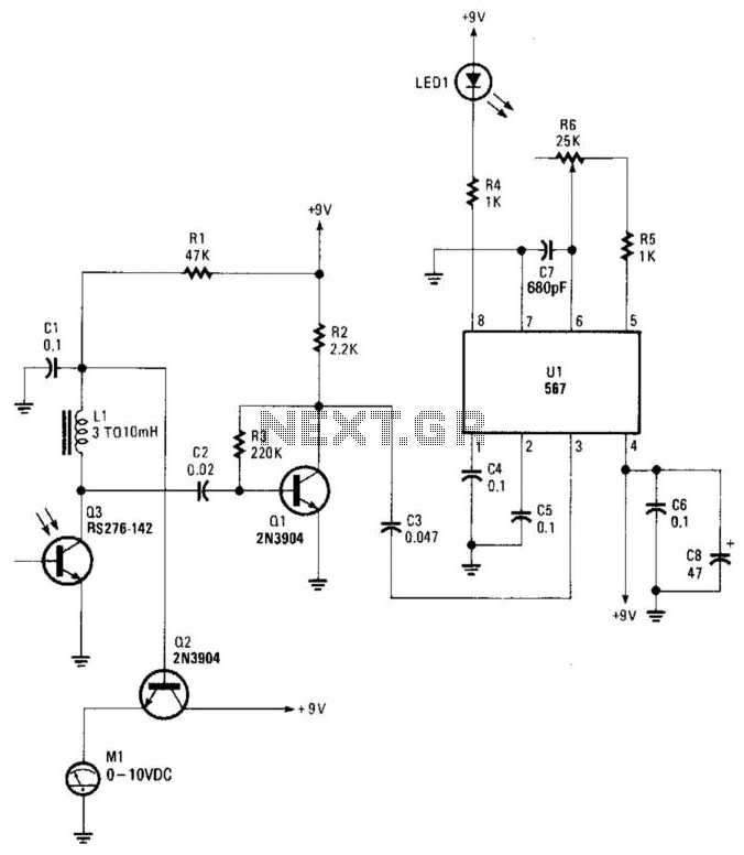
The circuit described involves several components working in conjunction to detect and measure modulated infrared signals. The IR phototransistor, Q3, serves as the primary sensor, converting the incident IR light into an electrical signal. This component is sensitive to specific modulation frequencies, allowing it to distinguish between different signals based on their modulation characteristics.
Q1 acts as an amplifier for the AC component of the signal detected by Q3. The amplification process enhances the weak signals produced by the phototransistor, ensuring that the subsequent components receive a sufficiently strong signal for further processing. The choice of Q1's configuration—whether as a common emitter or common collector amplifier—will affect the gain and overall performance of the circuit.
Q2 is responsible for driving a meter that visually indicates the strength of the incoming IR beam. The design of this section should consider the meter's calibration, as a strong IR signal results in a lower reading on the meter. This inverse relationship necessitates clear markings on the meter for easy interpretation, allowing users to quickly assess the signal strength.
U1, the tone decoder, plays a critical role in the system by identifying the specific frequency of the incoming modulated signal. The output on pin 1 is indicative of whether the received signal matches the expected modulation frequency, which is determined by the value of resistor R6. This resistor sets the reference frequency for the tone decoder, making it essential for proper operation. The low output from U1 during reception indicates a successful detection of the correct modulation, enabling further actions in the circuit, such as triggering an alarm or activating another device.
In summary, the described circuit effectively combines an IR phototransistor, amplification stage, a meter for visual feedback, and a tone decoder to create a robust system for detecting and measuring modulated IR signals. The careful selection of components and their configurations is vital for achieving the desired performance and accuracy in applications such as remote controls, optical communication systems, and other IR signal processing tasks. Q3 is an IR phototransistor that responds to a modulated IR beam. Q1 amplifies the ac component of the IR beam. Q2 drives a meter as a relative indication of the strength of the light beam. A strong beam gives a lower meter reading. U1 is a tone decoder that produces a low output on pin 1 during reception for an IR beam that is modulated with the correct tone frequency, determined by R6. 🔗 External reference
Related Circuits
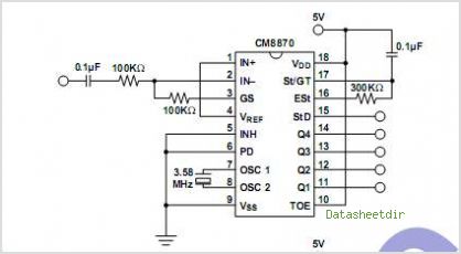
The CAMD CM8888 8888-2 is a fully integrated DTMF transceiver that features adjustable guard time, automatic tone burst mode, call progress mode, and a fully compatible interface for 8051 and 8086/8 microprocessors. It is manufactured using advanced CMOS technology,...
Wireless headphone transmitter and receiver systems are now widely available in the market, offering a variety of pricing options along with reliable technical specifications for various applications. These include wireless headphones for televisions, computers, and earbuds. A wireless headphone...
The tuned circuit consists of a variable capacitor and fixed air spaced coil. For the coil, wound between 10 and 20 turns of wire on an empty tube of around 1.5 inches diameter. The turns were spaced so that...
The regen is basically an oscillator circuit with a gain control that allows the user to adjust the feedback to a point just below oscillation or, quite often, just above the critical level such that a small oscillation is...
This Atmel integrated circuit operates at a clock frequency of 12 MHz, facilitating communication between an infrared receiver and a personal computer. This setup enables the processing of signals by infrared receiver software, such as Girder. When a valid...
This converter allows reception of six metre signals on a two metre receiver. It should therefore be useful for those with single or dual band sets that do not cover 50 MHz. More: To eliminate the need to obtain...