
Easy Crystal Impedance Checker Circuit
Testing the equivalent series resistance (Rs) of a crystal oscillator is crucial for ensuring compatibility with microprocessors and microcomputers. Incompatible crystals may lead to malfunctioning circuits, which can compromise the performance of electronic devices. The described testing setup leverages a sweep generator to provide a frequency signal that is varied until it matches the resonant frequency of the crystal under test. An oscilloscope is employed to visualize the output signals, allowing for real-time analysis of the crystal's behavior.
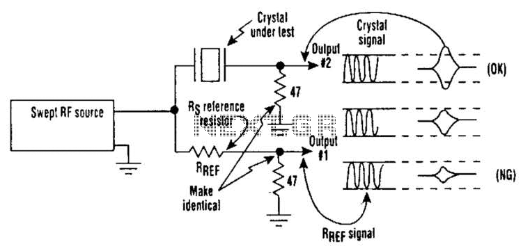
The three resistors in the circuit serve specific roles: one acts as a reference resistor, while the others may be used to create voltage dividers or limit current in the testing circuit. The relationship between the amplitudes of output 1 and output 2 provides critical information about the crystal's Rs value. If output 2 surpasses output 1, it indicates that the crystal's Rs is lower than the reference, suggesting it is suitable for use. If output 2 does not exceed output 1, this indicates that the Rs is too high, which could lead to inefficiencies or failure in the oscillator circuit.
This testing method is advantageous due to its simplicity and effectiveness, allowing engineers to quickly ascertain the suitability of a crystal for a given microprocessor application. Proper selection and testing of crystals can significantly enhance the reliability and performance of electronic systems, particularly in timing applications where precision is paramount. On occasion, microprocessors/microcomputers and microprocessor crystals just aren`t compatible with each other. Many microprocessor data sheets specify maximum values for a crystal`s equivalent series resistance (Rs) that aren`t met by some crystals advertised for microprocessor/ microcomputer use.
As a result, a crystal with an Rs value greater than the maximum specified for the chip might cause problems, such as a balky or even inoperative clock oscillator. To tackle this problem, a suspected crystal can be given a quick check for Rs with a simple test setup that consists of a sweep generator, oscilloscope, and three resistors (see the figure).
When the frequency source is brought to the crystal`s frequency, output 2 will maximize. If it exceeds the amplitude of output 1, the crystal`s Rs value will be less than the Rs reference resistor`s value. If it doesn`t exceed output l`s amplitude, the crystal`s Rs value is too large. 🔗 External reference
Related Circuits
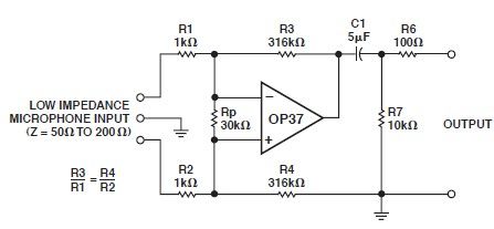
This microphone preamp schematic is an electronic circuit project utilizing the OP37 operational amplifier from Analog Devices. It functions as a fixed-gain transformerless microphone preamp, amplifying differential signals from low-impedance microphones by 50 dB, with an input impedance of...
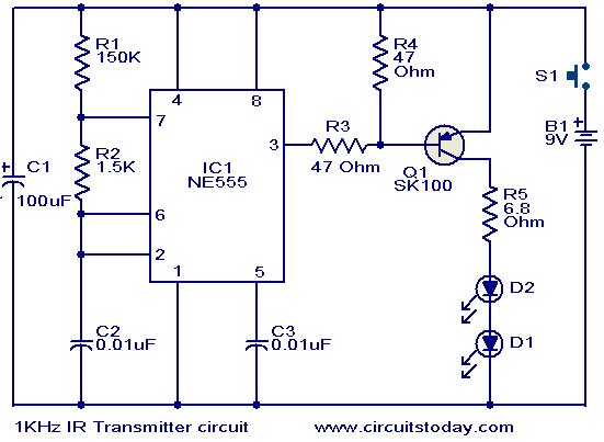
This circuit was designed in response to a request for a 1 kHz infrared (IR) transmitter circuit suitable for remote control applications. It is intended to serve as a low-power IR transmitter with an operating frequency of 1 kHz,...
When the doorbell switch K1 is pressed, the doorbell rings and LED D3 lights up. If there is no one to answer the door, guests will leave, but D3 remains illuminated, indicating that visitors have arrived. The circuit includes...
This tracking transmitter consists of four distinct subassemblies: a free-running multivibrator, a transmit switch, an audio-tone generator, and an FM transmitter. The multivibrator, which produces a pulse width with a pulse separation of 1500 ms, is built around Q1...
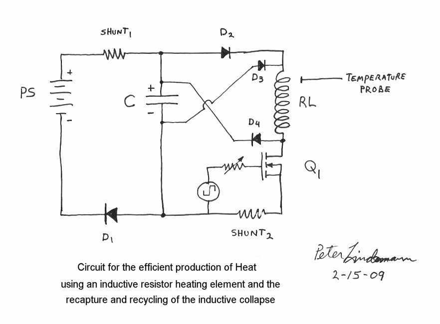
Rosemary's original test circuit is shown in the article she tried to have published in a refereed scientific journal, but the submission was always rejected. In the last 5 months, I have had extensive email correspondence, and numerous telephone...
The circuit amplifier and attenuator control video detector consists of a composition for the synchronization channel. The synchronization interval is where the gain circuit is increased. The described circuit involves an amplifier and an attenuator that work together to control...