
IR Remote Control of PICAXE Micro
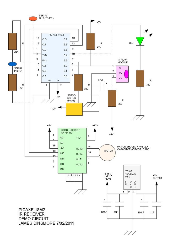
The PICAXE microcontroller is designed for simplicity and ease of use, particularly in educational and hobbyist applications. The code structure typically involves a main loop that utilizes the `irin` command to monitor incoming infrared (IR) signals. This command allows the microcontroller to detect signals from an IR remote control or other IR transmitting devices.
Upon receiving a valid code, the PICAXE stores this value in a variable for further processing. The main loop's continuous operation ensures that the system remains responsive to incoming signals, facilitating real-time interaction with the user or other devices.
In practical applications, this setup can be used for various purposes, such as controlling electronic devices, navigating menus, or triggering specific actions based on the received IR codes. The simplicity of the PICAXE programming environment allows users to easily modify and expand the code to suit their specific project needs, making it an ideal choice for beginners and those looking to prototype quickly.
For a complete schematic, additional components such as the IR receiver module, power supply, and output devices (like LEDs or motors) would be incorporated, ensuring that the entire system operates cohesively.The PICAXE basic code is easy: the main loop keeps looking for a signal from the IR receiver via the irin command. When it gets a code, it places in.. 🔗 External reference
Related Circuits

Efforts were made to minimize the number of wire jumpers on this board, but space constraints arose due to the integration of the microcontroller and motor driver on a single board. The design would have been cleaner without the...

The purpose of this circuit is to maintain a permanent magnet DC motor at a constant speed, which is set externally. This is achieved by monitoring the current flowing through and the voltage across the motor's brushes. The schematic for...
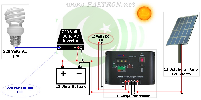
A solar charge controller is an electronic device used in solar system installations to regulate the amount of charge directed toward a battery from a solar panel. Charge controllers come in various types and ratings. The term "charge controller"...
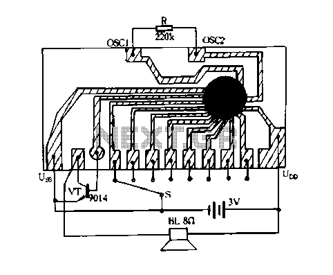
Constantly changing light and sound analog controller circuit 05 The circuit described is an analog controller designed to modulate light and sound in a dynamic manner. This type of circuit typically employs a combination of resistors, capacitors, and operational amplifiers...
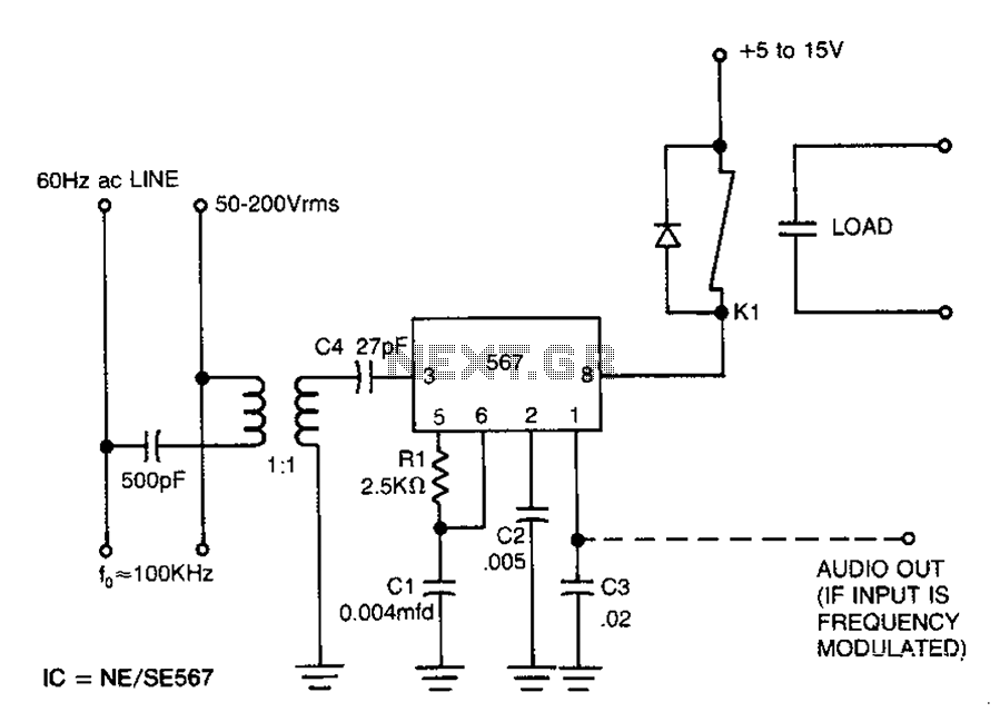
Carrier current remote control device or intercom circuit diagram as follows: The circuit diagram for a carrier current remote control device or intercom system typically involves the use of carrier current technology to transmit audio signals over existing electrical...
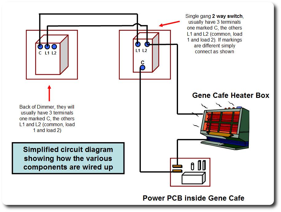
Enable the Gene to progressively lower the power applied to the heating element, allowing it to reduce heat instead of switching on and off. This minimizes the temperature gradient within the drum and the maximum temperatures that the beans...
Warning: include(partials/cookie-banner.php): Failed to open stream: Permission denied in /var/www/html/nextgr/view-circuit.php on line 713
Warning: include(): Failed opening 'partials/cookie-banner.php' for inclusion (include_path='.:/usr/share/php') in /var/www/html/nextgr/view-circuit.php on line 713