
Gene Cafe Dimmer Control Mod
The described modification allows for precise temperature control during the roasting process, enhancing the overall quality of the roasted beans. The use of a Varilight dimmer is particularly beneficial due to its robust construction, which supports the necessary modifications for increased heat sink capacity. This modification involves careful disassembly of the Gene, ensuring that the original components are not damaged during the process. The aluminum heat sink must be adequately shaped to provide optimal thermal contact with the dimmer module, which is essential for efficient heat dissipation.
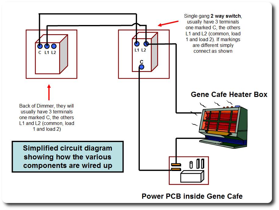
When drilling holes in the pattress boxes, it is crucial to ensure that the holes align correctly for the wiring to avoid complications during assembly. The addition of ventilation holes is a practical enhancement that facilitates better airflow, preventing overheating and ensuring the longevity of the components involved.
The two-way switch configuration allows for seamless transition between direct and dimmed operation, providing flexibility in controlling the roasting temperature. This is particularly useful during different stages of the roasting process, where precise temperature management can significantly affect the final product.
The operational strategy of starting with a higher temperature and then switching to the dimmer for finer control represents a practical approach to managing the roasting profile. The recommendation to avoid setting the Gene's built-in temperature control too close to the desired temperature is a critical insight that helps prevent unwanted cycling, which can adversely affect the roasting outcome.
Overall, this modification not only improves the efficiency of the roasting process but also enhances the consistency and quality of the roasted beans, making it a valuable upgrade for those looking to achieve superior results in their coffee roasting endeavors.Enable the Gene to progressively lower the power applied to the heating element, so that rather than switching it on and off, it simply got less hot, minimising the temperature gradient within the drum and the overall maximum temperatures the beans are subjected to near the inlet end of the roasting chamber. Warning: a reasonable level of competen ce is required and no guarantee is given that these guidelines are error free, you undertake all work at your own risk, we take no responsibility for anything that happens Assuming you have most of the bits and bobs such as connectors and duck tape, the cost of the project will be around £23 or less. The Varilight dimmer ( ) has been specially selected as its high quality of construction allows for easy and simple modification, with the minimum of work and risk to the component (I am not sure how well other manufacturers dimmers will work).
3 Add some extra heat sink capability. First pull off the knob and undo the nut as shown by the arrows. This will allow you to remove the dimmer module and it`s heat sink. You want to end up with something that looks like the diagram below. The piece of Aluminium simply has a hole drilled out (elongated hole is better) and is bent as shown below. The hole is large enough for the threaded part of the dimmer module (the part the but screwed on to earlier) to be passed through it and the replaced and re-tightened.
As long as your piece of Aluminium is flat and not too thick. The existing heat sink of the dimmer is in full contact with it and when the module is replaced sufficient pressure is applied to form an excellent thermal contact area. You will actually be able to use a heat sink much smaller than mine e. g. omit the folding back on itself . me I just like IKB type design. Your dimmer should look something like this Congratulations, your dimmer will now easily handle the 1250+ watts of the heating element with no problems or further modification required.
I should add though that it is extremely important to have a good contact between the extra heat sink and the existing heat sink of the dimmer and ideally, use thermal past at the junction of the two heat sinks. Dissassemble the Gene as shown here The overview of what you need to do is shown here (click to enlarge) Use a drill with a HSS (High Speed Steel) bit to drill holes in the pattress boxes, one for the cable from the gene, and then 2 holes that line up between the boxes for the dimmer wires.
To finish off the wiring in the pattress boxes, simply finish wiring the dimmer to the 2 way switch as shown below (click to enlarge). After some time using this modification, I have decided to drill some extra ventilation holes in the rear of the pattress box, using the existing push out points.
Screw everything together and add some duck tape to form the 2 separate pattress boxes into a single unit. I found this better than glue, which simply slides off and is messy. It also allows you to separate them in future if desired. Label your switch DIM and DIR, dimmer and direct . The finished roaster (click to enlarge). 4 I start my roasts with the Gene set to 240C and the switch in the DIR position, so that the dimmer is not being used and for at least the first 5 minutes and possibly up to 1st crack, I won`t be using the dimmer module.
As soon as I want to control the temperature or slow the ramp, I switch to DIM and start using the dimmer (which I leave initially in the fully bright position). I find that depending on the ambient temperature and the temperature I want to maintain my roast at .
around 1050 to 1100 watts in winter (possibly 1000W in summer), is enough to maintain the temperature without the element switching on and off. My Gene temperature control knob is now simply a safety or limiter on the maximum temperature the roast can achieve.
Note: don`t set the genes own temperature control too close to the desired temperature as if the Gene reaches it, it will switch off the element and drop nearly 3/4C, something we want to avoid (This is why I use 240C). So if your voltage is good, you can control part of the ramp up and certainly have a controlled drying stage if you want to .
for beans which are reaching 1st a little rapidly again you can temper this. At and beyond 1st crack you can pretty much set whatever profile you desire. The temperature gradient within the drum when under dimmer control will be at the absolute minimum it can be. At the end of the roast, I switch back to direct to take the dimmer out of the circuit, because otherwise there will be a small voltage (50V) across the dimmer during the cooling cycle and as long as the Gene is physically plugged in.
with no load on the Dimmer (dimmer requires a 200W minimum load), I am not sure if this will have any effect on the triac within the dimmer, it`s unlikely but there is no point in taking chances. The other reason for having the two way switch, is that there is a 30W power loss within the dimmer, but of course NO power loss with the switch in "DIRECT" mode Initial results are very encouraging, roast quality is great, roasts are visually more even, especially on beans which tend to be a little uneven anyway.
Careful inspection will show a significant reduction (or absence) of Divots, Tipping or scorching. Interestingly roasts can actually be heard entering second crack, but the bean does not seem as dark as it would usually be when this happens, indicating the possibility or a more even roast throughout the internal structure of the bean. 🔗 External reference
Related Circuits
To complement the 60 Watt MOSFET audio amplifier, a high-quality preamplifier design was necessary. A discrete components topology using +24V and -24V supply rails was chosen, minimizing the transistor count while still achieving low noise, very low distortion, and...
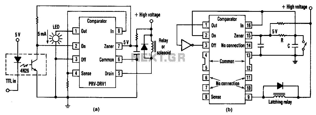
At half brightness, the lamp current is pulsed on and off by the voltage developed across the resistor and capacitor at the current-sense output. The current-sense output detects the lamp current. A basic pulse-width modulation (PWM) lamp-brightness control circuit...
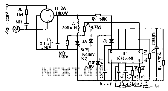
The synchronous vibration circuit operates with a control logic that includes three primary components. An internal oscillator is initiated by a synchronization pulse, transitioning to a low state immediately after the pulse. Upon power activation, the internal circuitry undergoes...
A very simple circuit that will find application in the case where you have a lot of telephones installed on a telephone line and would want to know if somebody of them is open. Thus, you will not be...
This simple circuit drives six LEDs in a Knight Rider scanner mode. Power consumption primarily depends on the type of LEDs used, especially when utilizing a 7555 (555 CMOS version). The Knight Rider scanner circuit is designed to create a...
As shown in the figure, D187 is a UART with its RX/TX signals connected through optocouplers N21, N22, and N29, providing complete optoelectronic isolation for the RS-485 communication interface receiver/transmitter D28 and microprocessor D211. D197 serves as a generator,...
Warning: include(partials/cookie-banner.php): Failed to open stream: Permission denied in /var/www/html/nextgr/view-circuit.php on line 713
Warning: include(): Failed opening 'partials/cookie-banner.php' for inclusion (include_path='.:/usr/share/php') in /var/www/html/nextgr/view-circuit.php on line 713