
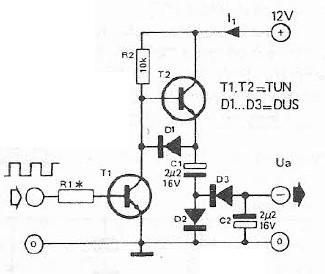
Constantly changing light and sound analog controller circuit 05
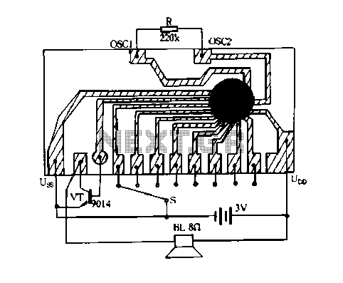
The circuit described is an analog controller designed to modulate light and sound in a dynamic manner. This type of circuit typically employs a combination of resistors, capacitors, and operational amplifiers to create varying signals that influence the intensity of light sources, such as LEDs, and the output of sound devices, such as speakers or buzzers.
In this specific design, the core functionality relies on the use of a variable resistor or potentiometer that adjusts the level of input signals. These signals are then processed through an operational amplifier configured in a feedback loop to ensure stability and responsiveness. The output can drive a light-emitting diode (LED) or a small speaker, providing a visual or auditory response that continuously changes based on the input parameters.
To implement this circuit, a power supply is required, typically in the range of 5V to 12V, depending on the components used. The circuit may also include a microcontroller to further enhance the control capabilities, allowing for complex modulation patterns and integration with other electronic systems.
The analog controller circuit can be enhanced by incorporating additional elements such as light sensors or microphones, which can adjust the output based on ambient conditions, creating an interactive experience. By fine-tuning the values of the passive components, the response time and sensitivity of the circuit can be optimized for specific applications, making it suitable for artistic installations, educational tools, or entertainment systems.
Overall, this circuit offers a versatile platform for exploring the interplay between sound and light, providing endless opportunities for creative expression and technological experimentation.Constantly changing light and sound analog controller circuit 05
Related Circuits
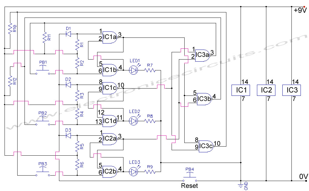
First Response Monitor, Input Selector, Game Circuit. This circuit is utilized for first response applications as it aids in monitoring various responses in games. The First Response Monitor circuit is designed to facilitate real-time monitoring and selection of input signals...
The circuits in Figure 1 and Figure 2 demonstrate specific advantages over the circuit presented in the Design Idea in EDN, titled "Circuit detects first event," published on May 3, 2001, page 89. The n-player first-event detection circuit provides...
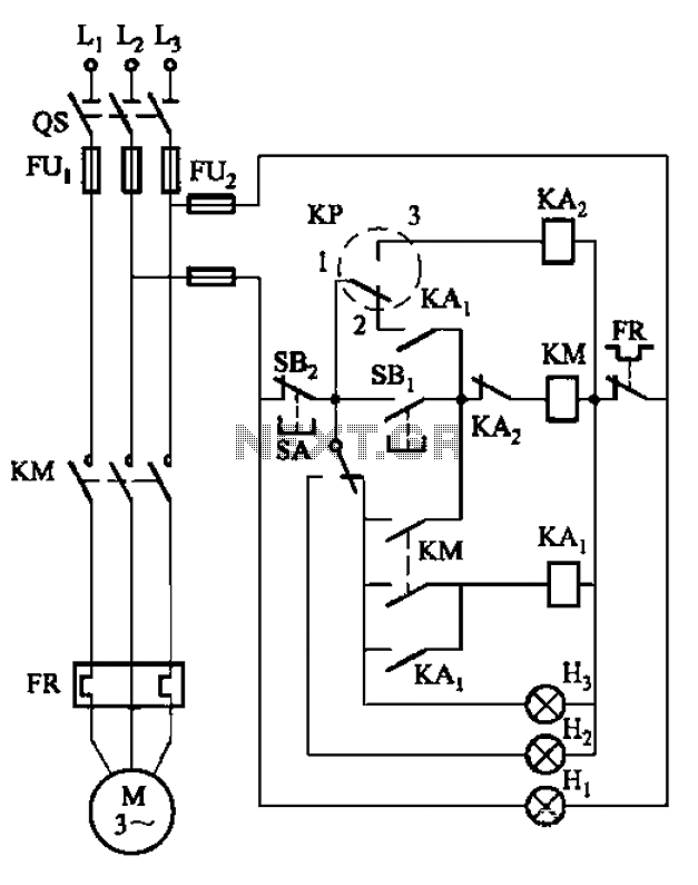
An air compressor is commonly utilized in electrical equipment factories and is typically controlled by electrical contacts. The circuit diagram is depicted in Figure 5-1. The circuit allows for both automatic and manual operation. In the diagram, KP represents...
Voltage inverter circuit design electronic project using few electronic components The voltage inverter circuit is a fundamental electronic project that converts direct current (DC) to alternating current (AC). This circuit is particularly useful in applications where AC voltage is required...

This circuit needs a Faraday shield, which is connected to 0V. To make this one wrap a tin foil around the coil and connect to 0V. Then you can use this circuit to find metal. Tune your mw radio...
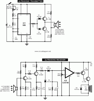
This circuit explains alternate wireless switching using an ultrasonic sensor. The distance of the switching range should be more than 10 meters. The described circuit employs an ultrasonic sensor to facilitate wireless switching, allowing for the activation or deactivation of...
Warning: include(partials/cookie-banner.php): Failed to open stream: Permission denied in /var/www/html/nextgr/view-circuit.php on line 713
Warning: include(): Failed opening 'partials/cookie-banner.php' for inclusion (include_path='.:/usr/share/php') in /var/www/html/nextgr/view-circuit.php on line 713