
IR Remote Control Receiver
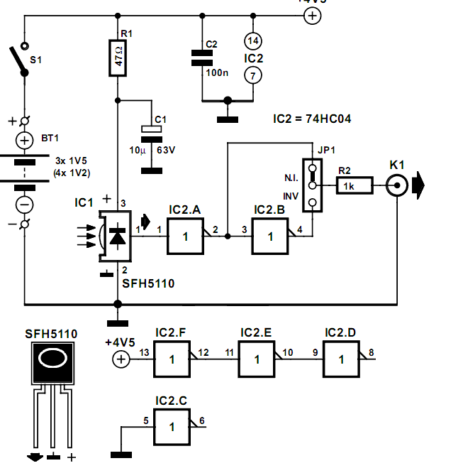
In audio system designs where components are split into separate units, it is common for only the amplifier to feature a remote control receiver module. This design choice is often driven by cost considerations, as integrating remote control functionality into every component can significantly increase the overall expense of the system.
To implement a remote control system effectively, the amplifier typically includes an infrared (IR) receiver that can interpret signals from a remote control device. The IR receiver is connected to the amplifier's microcontroller, which processes the signals and executes commands such as adjusting volume, changing input sources, or powering the unit on and off.
For systems where additional components, such as CD players or tuners, require remote control capabilities, a workaround can be established. By using a universal remote control, users can program the amplifier to relay commands to other components via discrete control signals, often utilizing a combination of wired connections and additional IR emitters placed in front of each unit.
This configuration allows for a streamlined user experience, enabling control of multiple audio sources from a single remote while maintaining a cost-effective design. In addition, systems can be enhanced with features like programmable macros, which allow users to execute a series of commands with a single button press, further simplifying operation.
Overall, the inclusion of a remote control receiver in the amplifier serves as a central hub for controlling an entire audio system, making it a practical solution for many users while balancing functionality and cost.With many audio systems consisting of separate units, you ll often ?nd that due to economic reasons only the amplifier has a remote control receiver modul.. 🔗 External reference
Related Circuits
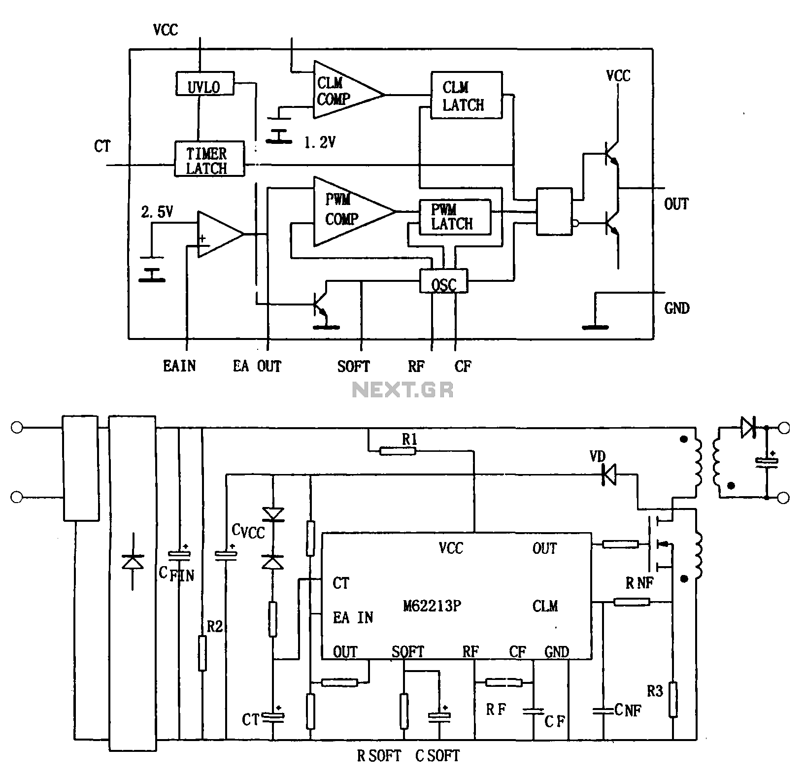
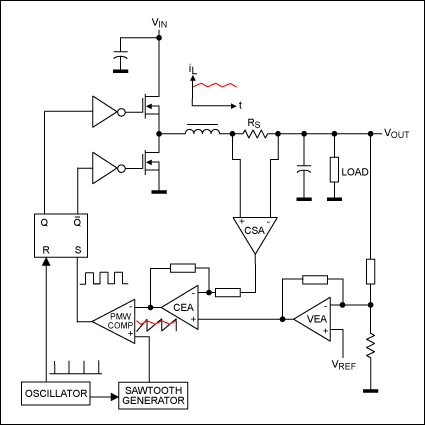
Figure (a) illustrates a block diagram of the internal architecture of the M62213FP, which is a high-speed switching power supply controller. This device includes an oscillator, PWM comparator, error amplifier, output circuit, over-voltage protection, timing latch circuit, over-current protection...
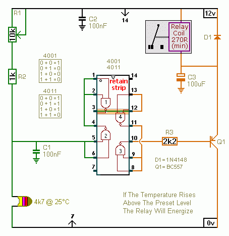
A CMOS 4001 or a CMOS 4011 can be utilized in this circuit, as both contain four two-input gates. The inputs of each gate are connected together, allowing them to function as simple inverters. This means that when both...
Constantly changing light and sound analog controller circuit 01 The described circuit functions as an analog controller designed to modulate light and sound outputs in a dynamic manner. This circuit typically integrates various electronic components, including resistors, capacitors, transistors, and...
As high-performance microprocessors require increased power in automotive multimedia and telematics, commonly referred to as infotainment products, several well-known issues arise, including noise susceptibility, electromagnetic interference (EMI), and loop compensation, among others. Average current-mode control (ACMC) assists in mitigating...
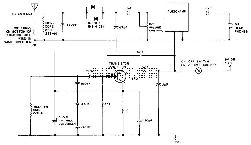
This circuit is designed for operation in the 80m band. It utilizes a 365-pF variable capacitor, specifically intended for the broadcast band, which should be equipped with a vernier drive featuring a six-to-one tuning ratio. This configuration enhances the...
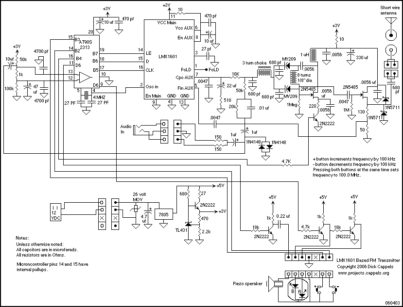
An LMX1601 Phase locked loop, a discreet FET VCO, and an AVR microcontroller combine to make a stable, easy to use monophonic FM transmitter that includes an audio activated switch that turns the transmitter on only when it is...