
Switching power supply from the high-speed switching power supply controller M62213FP
The M62213FP is designed for high efficiency and reliability in power supply applications. The internal oscillator generates a clock signal that drives the PWM comparator, which modulates the output voltage based on feedback from the error amplifier. The error amplifier compares the output voltage to a reference voltage and adjusts the duty cycle of the PWM signal to maintain a stable output. The over-voltage protection circuit monitors the output voltage and disables the switching operation if the voltage exceeds a predetermined threshold, ensuring the safety of connected components.
The timing latch circuit plays a crucial role in controlling the switching operation, providing a defined period during which the output can respond to changes in load conditions. The over-current protection circuit limits the output current to prevent damage to the power supply and connected devices. The soft-start feature gradually increases the output voltage during startup, reducing inrush current and minimizing stress on the components.
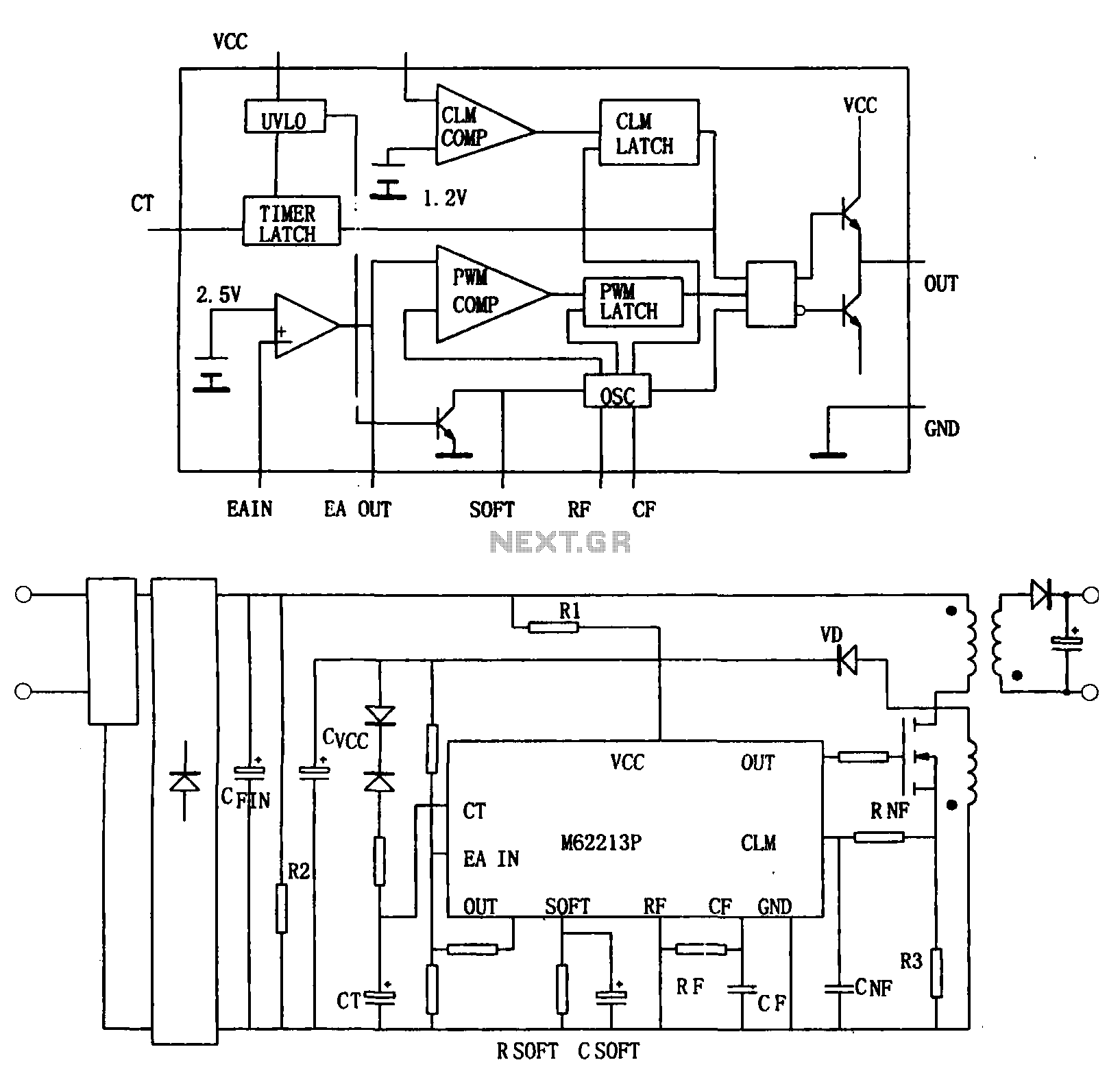
The design of the M62213FP allows for flexibility in application, with the ability to adjust the output voltage and current characteristics through external components. The integration of noise filtering components enhances the stability of the power supply, making it suitable for sensitive electronic devices. Overall, the M62213FP is an effective solution for high-speed switching power supply applications, combining advanced features with ease of implementation.Figure (a) shows a block diagram of the internal structure of the M62213FP. M62213FP is a high speed switching power supply controller. It consists of an oscillator, PWM compar ator, error amplifier, the output circuit, over-voltage protection and the timing of the latch circuit, over-current protection circuit and soft-start circuit. Switching frequency of 700kHz, the peak output current of 1A, push-pull output circuit, before the start of the current circuit is very small, typically 130 A, beginning with the start-stop voltage difference is large, starting starting voltage is 12.5V, start stop voltage of 8.3V, this would reduce the input smoothing capacitor.
On-chip high-speed current limiting, overvoltage and timed lockout, dead-time control and soft start, optocoupler feedback with direct excitation of the error amplifier output to prevent malfunction at low voltage functional circuits. Few external components can constitute function more perfect switching power supply.Figure (b) by high-speed switching power supply switching power supply controller configured as shown M62213FP.
The power output pulse on-time is determined by the resistor connected to the SOFT side, if a capacitor in parallel with this resistance, the start-time increases, so that you can achieve a soft start. M62213FP itself at start operating voltage, R1 is rectified by a voltage provided by the AC power source; normal operation from the flyback transformer of a winding to provide rectified by the rectifier diode VD, a voltage proportional to the output voltage at this time, therefore, also used for feedback control and overvoltage detection.
To prevent malfunction due to noise, filter access RNF and CNF constituted noise filtering.
Related Circuits
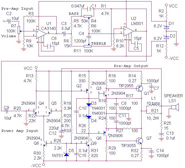
The circuit power amplifier depicted is a schematic design for a power amplifier with an output power of 70 watts, operating in Class AB mode. This power amplifier circuit is equipped with a tone control circuit. The 70-watt power...
It is possible to apply switch-mode techniques to a silicon CMOS semiconductor process to create a current-mode power amplifier with high gain and efficiency for use in 2.4-GHz wireless applications. Amplification at 2.4 GHz is essential for various wireless...
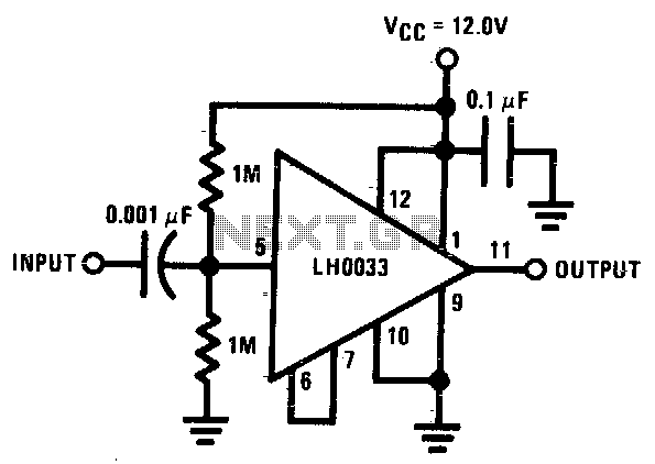
The input is DC biased to the mid-operating point and is AC coupled. Its input impedance is approximately 500K ohms at low frequencies. For DC loads referenced to ground, the quiescent current is increased by the load current set...
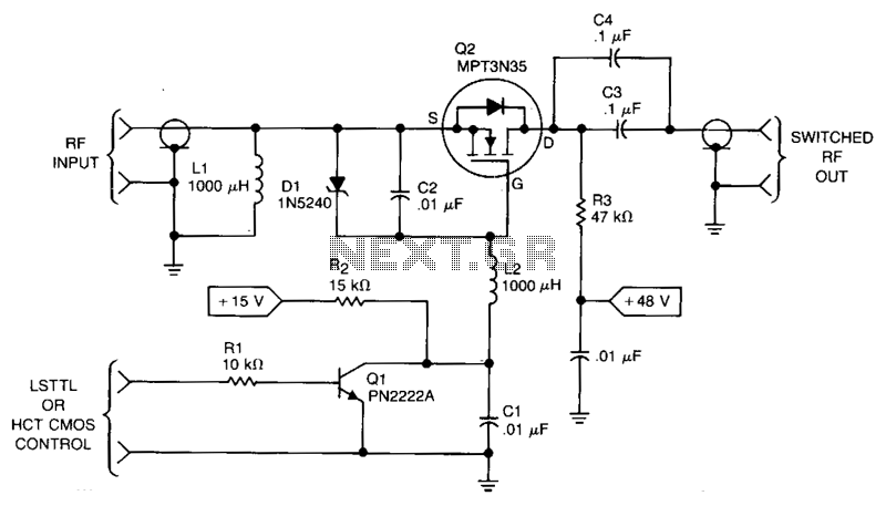
This RF power switch operates at 1.7 MHz with a 50-V source and load. Its on-loss is 0.2 dB, and its off-isolation is 30 dB. It provides 40-W PEP, 45 V_RMS, and 0.9 A_PEAK. The control input can come...
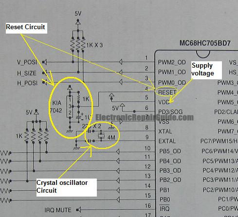
The difference between these two ICs. A microcontroller is a specialized type of microprocessor designed to be self-sufficient and cost-effective, while a microprocessor is typically intended for general-purpose use, such as in personal computers (PCs). The microcontroller integrates several...
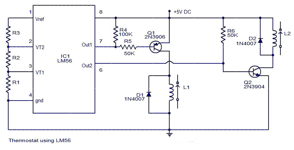
As summer approaches, many individuals focus on staying cool during hot days. For some, this means turning on the air conditioner and enjoying a cold beverage. However, it is essential to consider how to maintain the temperature of radio...