
Constantly changing light and sound analog controller circuit 01
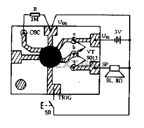
The described circuit functions as an analog controller designed to modulate light and sound outputs in a dynamic manner. This circuit typically integrates various electronic components, including resistors, capacitors, transistors, and operational amplifiers, to facilitate the continuous variation of light intensity and sound frequency or volume.
The core of the circuit may involve a light sensor, such as a phototransistor or a photoresistor, which detects ambient light levels and feeds this information into an operational amplifier. The output from the amplifier can then drive a light-emitting diode (LED) or a series of LEDs, creating a visual display that changes in response to the detected light levels.
For sound modulation, the circuit can utilize a similar approach with a microphone or sound sensor that captures audio input. This audio signal can be processed through an analog filter or a modulation circuit, which may include components like capacitors and inductors to shape the output sound wave. The final output can be directed to a speaker or piezo buzzer, allowing for variable sound production based on the input signal.
Additionally, the integration of a microcontroller may enhance the circuit's capabilities, allowing for programmable features such as different light patterns or sound effects. This can be achieved through the use of pulse-width modulation (PWM) to control the brightness of the LEDs and the volume of the sound output. The overall design emphasizes flexibility and responsiveness, making it suitable for applications in interactive installations, art projects, or educational demonstrations in electronics.
Safety considerations should also be taken into account, ensuring that all components are rated for the appropriate voltage and current levels to prevent damage or hazards during operation. Proper grounding and shielding techniques may be employed to minimize interference and ensure stable performance of the circuit.Constantly changing light and sound analog controller circuit 01
Related Circuits
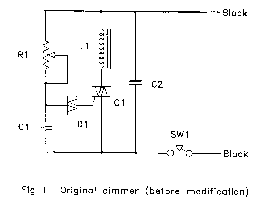
The circuit (before flameout) worked like this: device Q1 is a triac, which is a power-switching device. When triggered, it switches to a fully conducting state and stays that way until the current passing through it goes to zero....
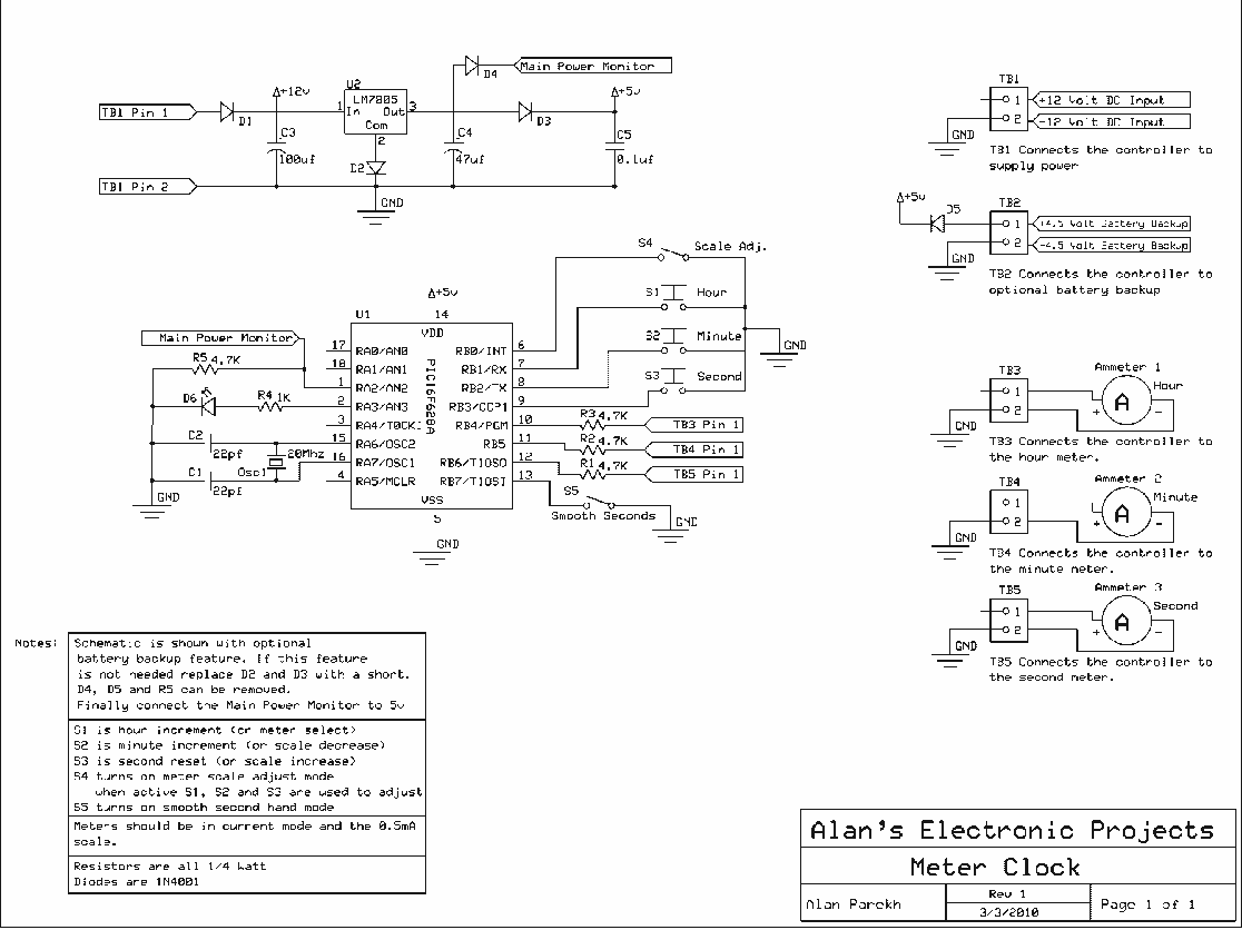
The Multimeter Clock consists of three multimeters, the first meter displays hours, the second displays minutes and the last displays seconds. A 16F628A PIC microcontroller keeps track of time and outputs a calculated current to each meter to display...
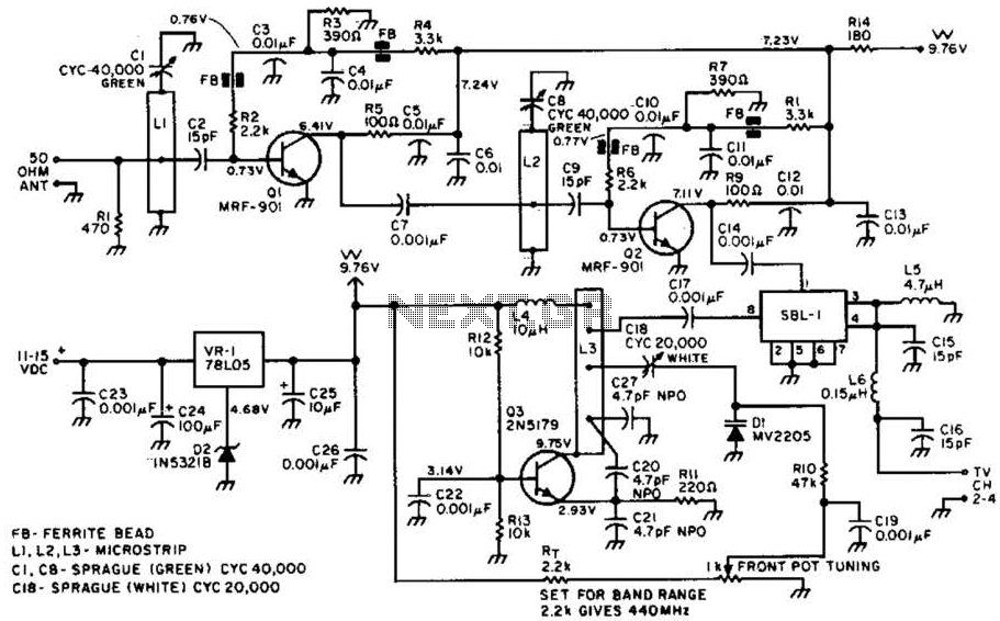
Most ATV (Amateur Television) transmitters operate using a Double Sideband (DSB) signal, while commercial television stations utilize a Vestigial Sideband (VSB) signal. This distinction is leveraged in this converter to utilize the lower sideband, thereby reducing interference from repeaters...
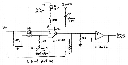
This design is for an interpolating scanner, a circuit featuring multiple signal inputs, a control voltage input, and a signal output. The output selectively transitions between inputs, smoothly fading from one to the next as the control voltage increases....
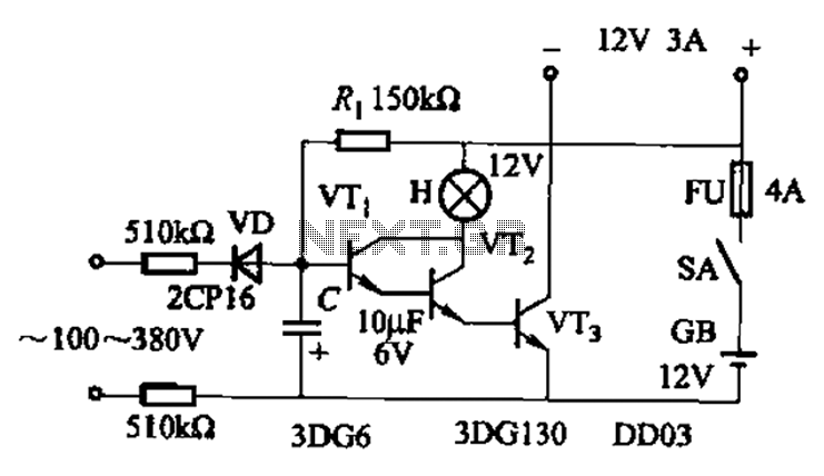
An AC-DC power supply without a power switching circuit is typically utilized for lighting load circuits. Once the power grid is restored, the standby power supply automatically switches on. An automatic switching circuit using a transistor is implemented, with...
This circuit is designed to connect stereo outputs from four different sources or channels as inputs, allowing only one of them to be selected and connected to the output at any given time. When the power supply is turned...
Warning: include(partials/cookie-banner.php): Failed to open stream: Permission denied in /var/www/html/nextgr/view-circuit.php on line 713
Warning: include(): Failed opening 'partials/cookie-banner.php' for inclusion (include_path='.:/usr/share/php') in /var/www/html/nextgr/view-circuit.php on line 713