
IR Remote Control Repeater
The schematic for this IR distribution system is structured to ensure efficient signal management and device interaction. The Microchip PIC 16F877 microcontroller acts as the central processing unit, executing the firmware that dictates the operational logic and timing for IR command distribution. The design incorporates a modular approach, allowing for easy scalability and adaptability based on user requirements, such as the choice between simple and deluxe modes.
In simple mode, the reliance on internal pullup resistors minimizes component count, making it a cost-effective solution for basic IR command distribution. Meanwhile, the deluxe mode enhances functionality by providing feedback on device connectivity through the use of external resistors and status LEDs, allowing users to monitor the operational status of connected devices easily.
The IR output section, utilizing Port A bits 0 through 3, is critical for modulating the IR signals at the standard 40kHz frequency, ensuring compatibility with a wide range of IR receivers. The careful design consideration for compensation of delays in the IR receivers demonstrates a thorough understanding of practical electronics and user experience, ensuring that the system operates reliably under various conditions.
Overall, this IR command distribution system exemplifies a well-thought-out design that balances functionality, adaptability, and user feedback, making it suitable for modern A/V setups in residential environments.This system is used to distribute IR commands around your house. This is useful if you have A/V equipment in one room that you want control from several other rooms. This project uses one Microchip PIC 16F877 to do all the work. The firmware is written in mostly C. It is compiled with Hi-Tech`s free PIC C compiler, available here. The schematics w ere drawn with CadSoft`s Eagle schematic drawing program, which is also free, and available here. Here is the main schematic. Click on it for a larger picture. It can be built one of two ways: simple input mode, or deluxe input mode. With deluxe input mode, the circuit can detect which inputs have something connected and will inform you via the status LEDs. If an LED is off, there`s nothing connected. If an LED is on, there is something connected. With simple mode, the circuit can`t tell you whether there`s something connected or not, but it does use less parts.
To select whether you want to simple or deluxe mode, you will have to change the BETTER_IR_EYE_MODE definition in the code and re-build. The code has been built in deluxe mode by default. Port B is used for the eight inputs. Each input is connected to one of two things: a piece of equipment that has some sort of remote control jack (like a Pioneer SR jack), or an IR receiver module, or "eyeball".
Either way, the signal must be +5V when idle and have 0V pulses when active. If you hook this to some equipment that has an output jack, it is expected that the equipment outputs a baseband (ie, demodulated) version of the modulated IR pulses from your remote controls. The inputs can be set up in simple mode or deluxe mode. In simple mode, no extra components are needed for the inputs. The internal port B pullup resistors are used. If an input is high, either nothing is connected, or it is idle. An input will pulse low when active. If an input gets stuck low, then there`s a problem with the device connected to that input. In deluxe mode, the system can determine if there is something connected or not. This is done by disabling the internal pullup resistors and supplying your own pull up/down resistor connected to port E bit 2.
This bit is continuously toggled between high and low to cause the resistors to toggle between pullup and pulldown. If nothing is connected to an input, its state will follow that of the port E bit. If something is connected, the input will be high all the time. An input will pulse low if active. If an input gets stuck low, then there`s a problem with the device connected to that input. Of course, without the status LEDs (discussed later), there`s no reason to use deluxe mode instead of simple mode.
The firmware has compensation for the on and off delay of the IR receivers. It turns out that with the receiver modules that I was using, it took four IR pulses before the module would trigger and assert its output, but it would take seven missed pulses before the module would return to the idle state. This would cause the IR blasters to send an extra three pulses. The firmware compensates for this by initiating a three-pulse delay before starting to send out the IR pulses.
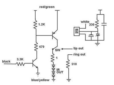
Port A bits 4 and 5 are outputs. Like the inputs, they are +5V when inactive and pulse 0V when active. They are expected to be hooked up to equipment that can accept this sort of signal (again, like a Pioneer SR jack). Port B bits 0 and 1 are special because they are both inputs and outputs. They are normally set up as inputs when the system is idle, but they get changed to outputs if another input triggers the system.
These are useful for rooms which contain equipment that you want to control, but you also want to be in this room and control equipment in other rooms. Port A bits 0 through 3 output a 40kHz modulated signal when the system is active. The outputs are 0V when idle but pulse +5V when active. It is expected that these are hooked up to IR LEDs. Port A IR output bits 0 and 1 🔗 External reference
Related Circuits
The Maxim MAX 6665 provides a complete temperature-dependent fan controller. It can switch fans operating at voltages of up to 24 V and currents of up to 250 mA. The IC is available from the manufacturer in versions with...
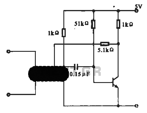
This circuit illustrates an oscillator that is controlled by an optocoupler, utilizing photoelectric coupling to drive a transistor. The oscillator circuit described operates by employing an optocoupler to provide electrical isolation between its input and output stages while allowing control...
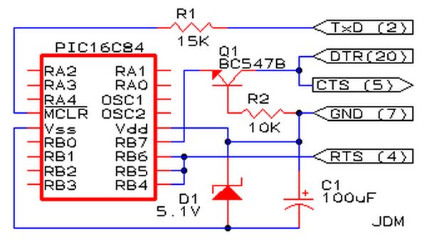
Affordable PIC Programmer. This programmer is compatible solely with the PIC16F84 microcontroller. It is reliable, as it rarely encounters errors, and functions well with nearly all computer systems, in contrast to some alternatives. The PIC programmer designed for the PIC16F84...

To maintain a constant speed of the motor under varying load conditions, a control application circuit is required. An H-Bridge circuit can be utilized to manage both the speed and direction of the motor. The accompanying diagram illustrates the...
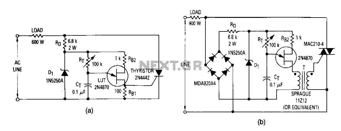
The most elementary application is a half-wave control circuit. The thyristor is acting both as a power control device and as a rectifier, providing variable power to the load during the positive half cycle and no power to the...
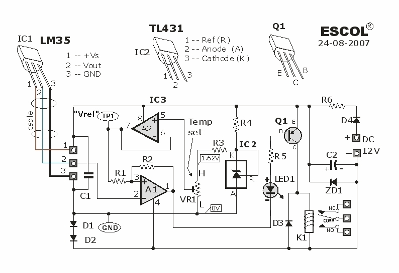
This temperature-controlled relay circuit is a simple yet highly accurate thermal control circuit that can be used in applications where automatic temperature regulation is required. The temperature-controlled relay circuit operates by monitoring the ambient temperature using a temperature sensor, such...
Warning: include(partials/cookie-banner.php): Failed to open stream: Permission denied in /var/www/html/nextgr/view-circuit.php on line 713
Warning: include(): Failed opening 'partials/cookie-banner.php' for inclusion (include_path='.:/usr/share/php') in /var/www/html/nextgr/view-circuit.php on line 713