
Phase Control Circuit
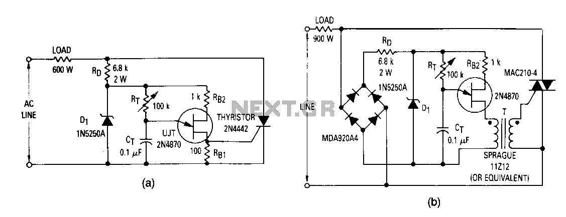
The described half-wave control circuit utilizes a thyristor, functioning as both a power control device and a rectifier. During the positive half cycle of the AC input, the thyristor allows current to flow to the load, effectively providing variable power. Conversely, during the negative half cycle, the thyristor blocks current, resulting in no power delivery to the load. This makes the circuit suitable for applications where control over power delivery is essential, such as in light dimmers or motor speed controls.
The circuit is designed for two-terminal operation, allowing it to be easily integrated into existing systems in place of a traditional switch. For scenarios requiring full-wave control, the circuit can be modified by incorporating a switch that short circuits the thyristor when the resistance of a variable resistor (Rr) is maximized, thus enabling full power delivery to the load.
To achieve full-wave control, additional components such as a bridge rectifier and a pulse transformer can be added. Switching from a Silicon Controlled Rectifier (SCR) to a TRIAC enhances the circuit's capability to manage both halves of the AC waveform. The bridge rectifier converts the AC input into a pulsating DC output, while the pulse transformer ensures isolation for the thyristor gate, eliminating the need for resistor R81, which would otherwise limit gate current.
In applications where a constant output voltage is necessary despite variations in line voltage, the introduction of a potentiometer (Pl) offers a practical solution. By adjusting this potentiometer, the circuit can maintain a consistent output voltage across a range of input conditions, thereby enhancing the reliability and performance of the system in variable environments. This configuration is particularly beneficial in sensitive electronic applications where voltage stability is crucial.The most elementary application is a half-wave control circuit. The thyristor is acting both as a power control device and as a rectifier, providing variable power to the load !luring the positive half cycle and no power to the load during the negative half cycle. The circuit is designed to be a two terminal control which can be inserted in place of a switch. If full-wave power· is desired as the upper extreme of this control, a switch can be added which will short circuit the SCR when R r is turned to its maximum power position.
Full-wave control might be realized by the addition of a bridge rectifier, a pulse transformer, and by changing the thyristor from an SCR to a TRIAC, shown in Fig 50-9b. In this circuit, R 81 is not necessary since the pulse transformer isolates the thyristor gate from the steady-state UJT current.
Occasionally, a circuit is required to provide constant output voltage regardless of line voltage changes. Adding potentiometer Pl to the circuits will provide an approximate solution to this problem. The potentiometer is adjusted to pro· vide reasonably constant output over the desired range of line voltage.
🔗 External reference
Related Circuits
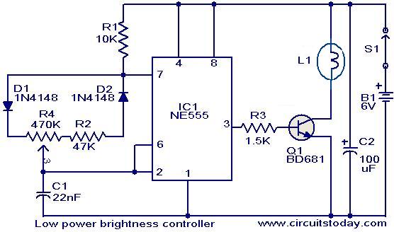
The circuit presented here is designed to control the brightness of low-power incandescent lamps. It utilizes the NE555 integrated circuit, configured as an astable multivibrator with a variable duty cycle. The output from the IC is connected to the...
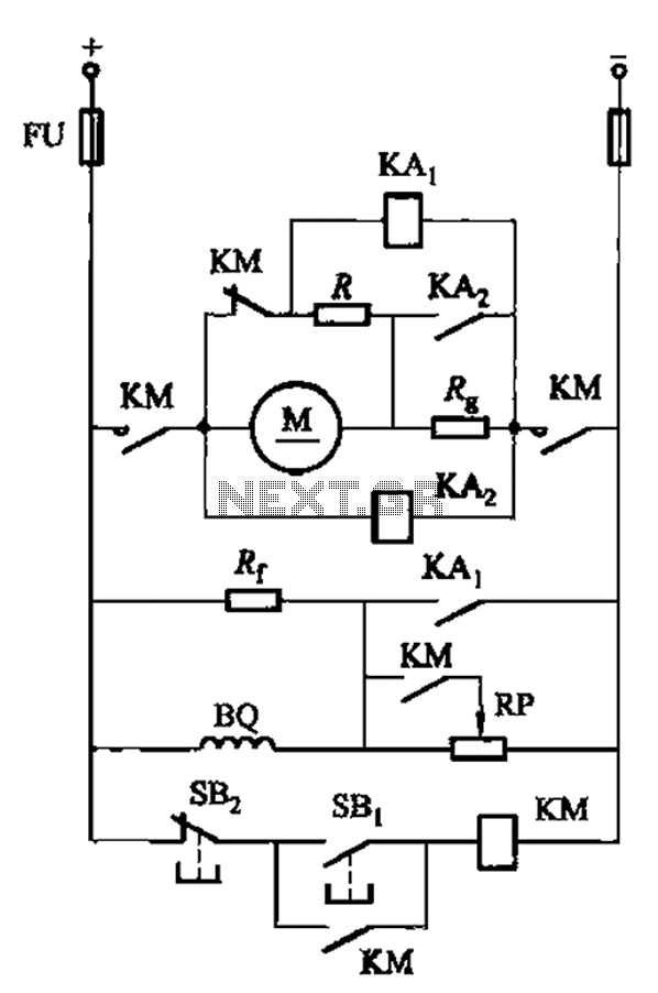
The circuit illustrated in Figure 3-197 features a dish adjust rheostat (RP) that allows for the adjustment of field current, which in turn modifies the motor speed. The circuit operates by utilizing a rheostat, which is a variable resistor that...
This circuit is designed to indicate, via a flashing LED, when room noise exceeds a predetermined threshold. The thresholds are set at three fixed levels: 50 dB, 70 dB, and 85 dB. Two operational amplifiers (op-amps) are utilized to...
All sound effects are generated internally by the HT2884 integrated circuit (IC). The device operates on a 3-volt battery but is compatible with any voltage ranging from 2.5 to 5 volts. Switch S1 functions as the on/off switch. The...
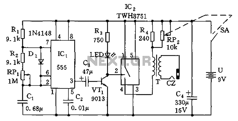
The circuit is composed of a 555 oscillator and an amplifier driver stage. It includes the 555 timer along with resistors R1, R2, RP1, capacitor C1, and other components forming a multi-harmonic oscillator. The frequency can be adjusted using...
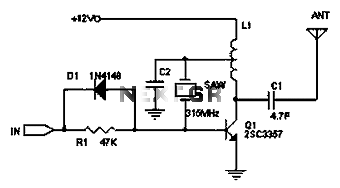
The circuit principle involves the use of an LC oscillator, which typically experiences significant frequency drift. Surface Acoustic Wave (SAW) devices have emerged as a solution to this issue, offering frequency stability comparable to that of crystal oscillators. SAW...
Warning: include(partials/cookie-banner.php): Failed to open stream: Permission denied in /var/www/html/nextgr/view-circuit.php on line 713
Warning: include(): Failed opening 'partials/cookie-banner.php' for inclusion (include_path='.:/usr/share/php') in /var/www/html/nextgr/view-circuit.php on line 713