
ir remote control tester
The infrared extender circuit is designed to effectively measure and compare the intensity of various infrared light sources, notably remote control units. The core components of the circuit include the SFH2030 photodiode, which is sensitive to infrared light, and the CA3140 operational amplifier configured in a differential mode. This configuration allows for precise amplification of the small current generated by the photodiode when exposed to infrared radiation.
The circuit operates by converting the detected infrared light into an electrical signal. When infrared light strikes the photodiode, it generates a current proportional to the intensity of the light. This current is then amplified by the CA3140 operational amplifier, which is essential for achieving a measurable output voltage. The output voltage at pin 6 of the op-amp can be directly correlated to the intensity of the incoming infrared light, making it possible to quantify the strength of various remote control signals.
The inclusion of LED1 serves as a visual indicator of infrared light detection. It provides immediate feedback to the user, signaling that the photodiode is receiving IR radiation. This feature enhances the usability of the circuit during testing and adjustments.
The output voltage can be monitored using a multimeter set to measure DC voltage, allowing for a straightforward comparison of the strength of different infrared remote controls. The circuit is designed to work effectively at a distance of approximately one meter, which is a common range for infrared remote controls. The relationship between the current through the photodiode and the output voltage is linear, with every microamp of current resulting in about one volt at the output.
It is important to note that not all operational amplifiers are suitable for this application. The CA3140 is preferred due to its characteristics, while common alternatives like the 741 or LF351 do not provide the necessary performance for this circuit. Additionally, the circuit can be powered by either a 12-volt power supply or a 9-volt battery, offering flexibility in power sourcing depending on the application requirements.
Overall, this infrared intensity measurement circuit presents a reliable solution for evaluating the performance of infrared light sources, particularly in the context of remote control devices.As I was developing my IR Extender Circuit, I needed to find a way of measuring the relative intensities of different Infra red light sources. This circuit is the result of my research. I have used a photodiode, SFH2030 as an infra red sensor. A MOSFET opamp, CA3140 is used in the differential mode to amplify the pulses of current from the photodi
ode. LED1 is an ordinary coloured led which will light when IR radiation is being received. The output of the opamp, pin 6 may be connected to a multimeter set to read DC volts. Infra red remote control strengths can be compared by the meter reading, the higher the reading, the stronger the infra red light. I aimed different remote control at the sensor from about 1 meter away when comparing results. For every microamp of current through the photodiode, about 1 volt is produced at the output. A 741 or LF351 will not work in this circuit. Although I have used a 12 volt power supply, a 9 volt battery will also work here. 🔗 External reference
Related Circuits
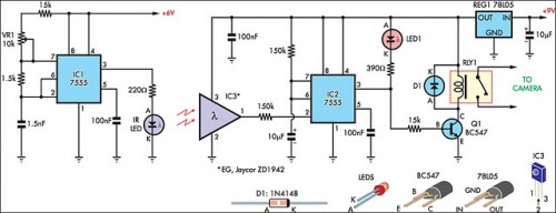
The IR detector (IC3) controls an LM 7555 CMOS timer (IC2) operating in monostable mode. When the beam is interrupted, IC2 is triggered, and its pin 3 output goes high for approximately half a second. This action extinguishes LED1...
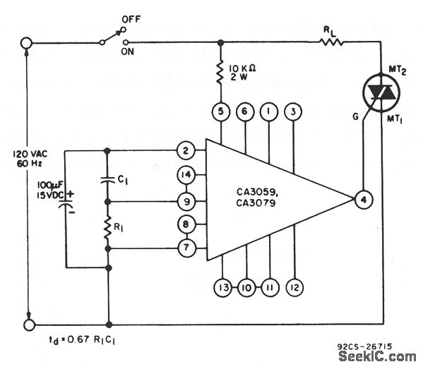
This circuit utilizes a CA3059 or CA3079 zero-voltage switch to manage the turn-on timing of a triac. The delay between the closure of the switch and the activation of the triac is determined by the resistor (R) and capacitor...
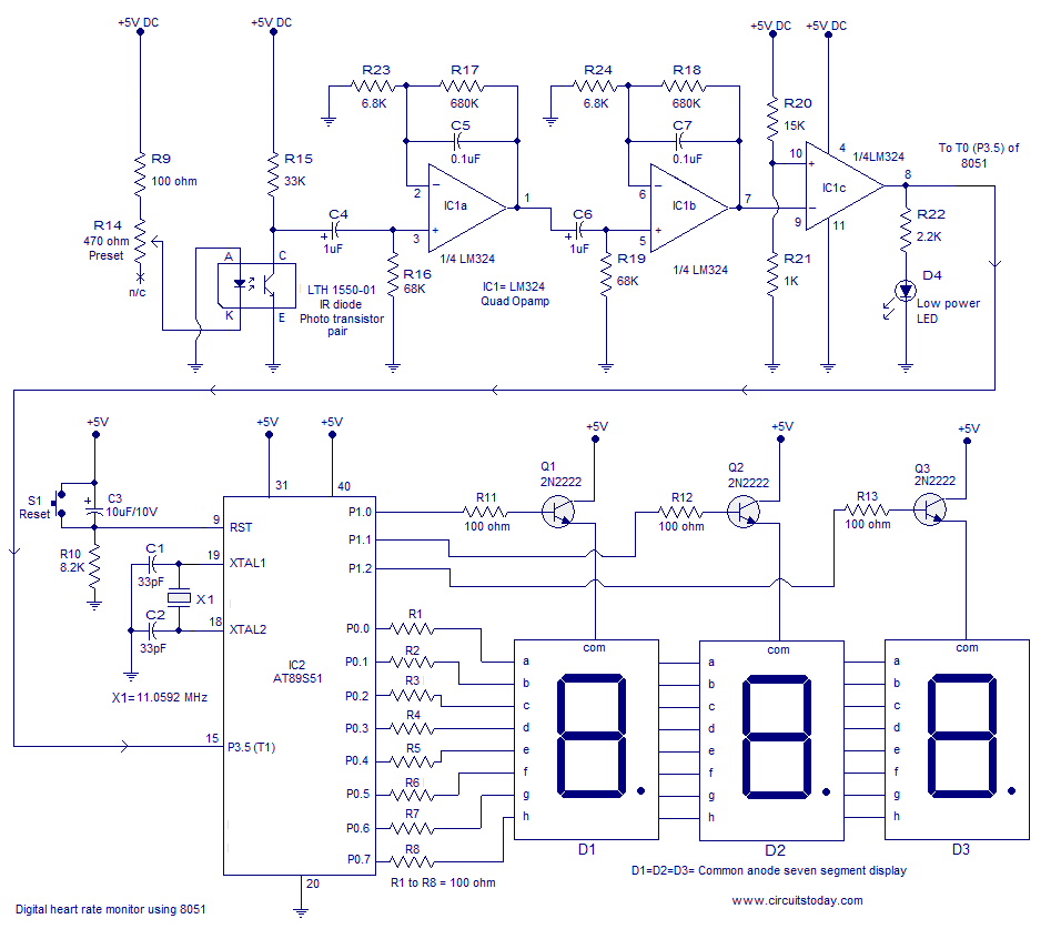
Heart rate monitor using an 8051 microcontroller. It measures the heart rate from the fingertip using an IR diode and phototransistor pair (Photoplethysmography). The AT89S51 microcontroller is utilized in this application. The heart rate monitor circuit operates based on the...
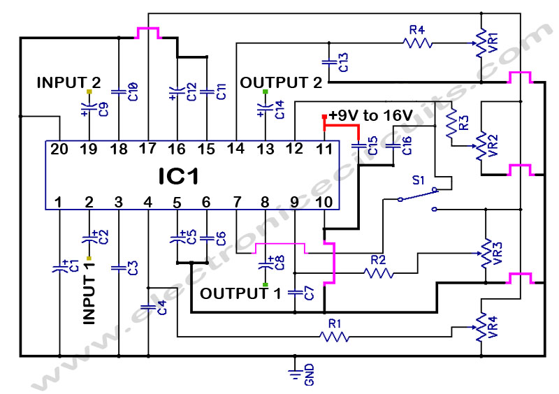
LM1036 Stereo Tone (Bass, Treble, Volume, Loudness, Balance) Controller Circuit. The LM1036 is a DC controlled tone (bass/treble), volume, and loudness controller designed for audio applications. The LM1036 circuit serves as an integrated solution for controlling various aspects of audio...
This hybrid circuit uses a mixture of transistors, an IC and a relay and is used to automatically open or close a pair of curtains. Using switch S3 also allows manual control, allowing for curtains to be left only...
Here's how you can make an electronic speed controller (ESC) for your remote control car, boat, or even an airplane using an old servo and some MOSFETs. Please note that this ESC has a very limited control range. Meaning...
Warning: include(partials/cookie-banner.php): Failed to open stream: Permission denied in /var/www/html/nextgr/view-circuit.php on line 713
Warning: include(): Failed opening 'partials/cookie-banner.php' for inclusion (include_path='.:/usr/share/php') in /var/www/html/nextgr/view-circuit.php on line 713